International Journal of Mechanical Engineering and Mechatronics (IJMEM)
ISSN: 1929-2724

Volume 1, Issue 2 - Year 2012 - Pages 1-8
DOI: 10.11159/ijmem.2012.001
Effects of a Scalloped and Rectangular Brace on the Modeshapes of a Brace-Plate System
Patrick Dumond, Natalie Baddour
University of Ottawa, Department of Mechanical Engineering
161 Louis Pasteur, Ottawa, Ontario, Canada K1N 6N5
pdumo057@uottawa.ca, nbaddour@uottawa.ca
Abstract - Shaping the soundboard braces on a wooden stringed musical instrument has long been a way in which instrument makers optimize their musical instruments. Reasons for these methods are scientifically not well understood. Various bracing patterns have successfully been used to create different-sounding wooden stringed musical instruments. These bracing patterns stimulate the modeshapes that are specific to the soundboard of the instrument. However, a higher adjustment resolution is required in order to specify the frequency spectrum of the musical instrument. This paper demonstrates how the shape of the braces affects the modeshapes of the vibrating system. A simple analytical model composed of a plate and brace is analyzed in order to see these effects. The results are plotted together for three cases: the plate by itself, the plate with a rectangular brace and the plate with a scalloped brace. For clarity, the modeshapes are analysed in 2D at different locations and along both the x and y directions of the plate. It is shown that any brace affects modeshapes for which the brace does not run along a nodal line. The different shapes of the brace are shown to affect different modeshapes by various degrees. If braces are stiffened at locations of maximum amplitude for a given modeshape, then that modeshape will be significantly affected. It is clear that by properly designing the shape of a brace, instrument makers can exert great control over the shape of the instrument's modeshapes and therefore also their frequencies.
Keywords: Scalloped Brace, Plate Vibration, Orthotropic Properties, Modal Properties.
© Copyright 2012 Authors - This is an Open Access article published under the Creative Commons Attribution License terms. Unrestricted use, distribution, and reproduction in any medium are permitted, provided the original work is properly cited.
1. Introduction
For centuries, stringed wooden musical instrument makers have been optimizing the sound of their musical instruments. Separately, the study of the physics of musical instruments has been on-going for some time. These studies have generally looked at sound production and sound radiation in musical instruments (Benade, 1990; Brooke and Richardson, 1993; Fletcher and Rossing, 1998; Chaigne, 1999; Richardson, 1999). Other studies have looked into modeling the instrument in order to better understand its function. The typical numerical approach is to use finite element analysis, but other methods are also used (Knott et al., 1989; Bretos et al., 1999; Elejabarrieta et al., 2001; Bécache et al., 2005). Since wood is a naturally inconsistent material, numerical models are often compared to real counterparts and parameters are adjusted to match experimental results (Elejabarrieta et al., 2000; A. Okuda and Ono, 2008). In parallel with these developments, the ability to achieve high dimensional tolerances has also been achieved in the instrument manufacturing industry. In spite of this, acoustical consistency is still lacking in manufactured wooden instruments (French, 2008). The primary reason for this is a lack of scientific understanding of the methods used by musical instrument makers in optimizing the sound of their instruments.
The soundboard of a stringed musical instrument is considered to be the most acoustically active part of a stringed musical instrument (Siminoff, 2002). Therefore, when optimizing the sound of the instrument, the soundboard becomes the most interesting component. Although it is clear that the bracing pattern of the soundboard has a significant effect on its modeshapes, very little scientific research on this subject exists. However, a very good historical timeline exists for its development (Turnbull, 1992; Natelson and Cumpiano, 1994). It is clear that bracing patterns of the soundboard emerged out of the need to allow the soundboard to vibrate as easily as possible while still maintaining structural integrity under string tension. Early guitars had gut strings which applied less tension to the soundboard. Early brace designs typically searched for ways of distributing this local string load over the entire soundboard. By doing so, the effectiveness of the bracing pattern was judged not only on how well it resisted the local string tension but also based on how clearly and how well the musical instrument projected its sound. Early designs included simple ladder bracing. Eventually, a fan design was developed by A. de Torres. Since the design proved to be very effective, it was adopted by many other instrument makers. Its widespread use eventually made it the industry standard. When classical and flamenco guitars started using nylon strings, tension in the strings remained similar, therefore tradition dictated the continued use of fan bracing. Although various builders have introduced small variations to brace structure over the years, very little has changed in the design of most instruments. In parallel, musicians started to seek larger and louder guitars. This led to the use of steel strings which produce much greater tensions. Typical fan bracing could not support this higher load. The solution came in the form of an X-brace design developed by C. F. Martin many years before. This design proved highly effective and has been the standard for steel string guitars ever since. The efficiency of these designs has been optimized empirically over the years with subjective analysis coming from critical musicians. More recently, lattice type bracing and double-top soundboards, where Nomex honeycomb paper is sandwiched between two thin layers of wood laminate, have seen a surge of interest among instrument makers, however their advantages are still under review by the community.
Very little scientific study has actually been performed on the effects of the various brace patterns and placements on the sound of the musical instrument. In fact, a look at the references in Fletcher and Rossing's review of musical acoustics shows little to indicate otherwise (Fletcher and Rossing, 1998). Conversely, based on years of experience, many renowned instrument makers including Cumpiano and Natelson as well as Somogyi believe that it is not so much the bracing pattern itself that has the greatest effect on the sound quality of the instrument but rather the skill in which inconsistent wood properties are accounted for in the construction of the instrument (Somogyi, 1993; Natelson and Cumpiano, 1994). Most knowledge of soundboard physics comes from technical articles, such as the article by Somogyi (Somogyi, 1993), written by instrument makers trying to explain what they have come to grasp naturally. In these articles, the dynamics of the soundboard motion are based on physical observation alone.
A few other works have looked at how different bracing patterns change the modal properties of the soundboard using Chladni's method and have then attempted to model the differences using finite element modal analysis (Sumi and Ono, 2008; Curtu et al., 2009). However, none of these papers explain how to effect specific changes in the bracing in order to produce specific modal patterns. An interesting paper by Lawther addresses the issue of avoiding certain frequency ranges in the context of braced structures through a modification of the bracing (Lawther, 2007). However, the goal was to avoid resonance rather than to tune the structure. In many ways, the bracing structure of a guitar is a scientifically misunderstood phenomenon which has built its success on the back of generations of practical experience. Although a good general idea of the physics behind the structure exists, no mapping of its dynamics has been thoroughly carried out.
However, it is clear that while bracing patterns have a direct effect on the modeshapes they cannot directly be used to choose the frequency spectrum of the soundboard. In most cases, bracing patterns completely reorganise the set of modeshapes. Thus a finer adjustment is necessary if only a change in frequency is sought. The most common way in which instrument makers adjust and optimize their musical instruments is by shaping the soundboard braces. Typically, the braces end up with what is known as a scalloped shape, as shown in Fig. 1.

Very little is known scientifically as to why instrument makers shape their braces and much debate still exists about the usefulness of scalloped braces. Although musical instrument makers have attempted to share their vast knowledge, a large gap still exists between their empirical methods and the scientific understanding and reasoning behind such methods. Thus, the goal of this paper is to demonstrate the effects of using a shaped brace on the modeshapes of a soundboard. A previous study has looked at the effects of brace shape on the frequencies of the system (Dumond and Baddour, 2012), but to the best of the author's knowledge, the effect of brace shape on the system's modeshapes has not been previously explored in the literature.
2. Model
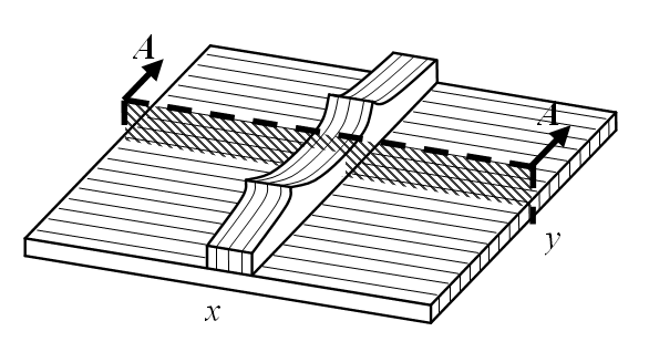
A simple analytical model is used to investigate the effects of a shaped brace on the modeshapes of a rectangular plate. Fig. 2 shows a typical soundboard section supported by a single brace. The brace is used to reinforce the structurally weaker direction of the plate.
The assumed shape method is used in the analysis (Meirovitch, 1996). Since this is an energy method, the kinetic and strain energies of the plate must be developed. Certain assumptions are made in creating the model. The brace is modeled as a thicker section of the plate. The plate is considered thin and linear Kirchhoff plate theory is used. Although, as shown in Fig. 2, the grain of the plate and brace are perpendicular to each other, the way in which the kinetic and strain energy are added force the grain of the plate to be parallel to the brace between x1 and x2 in the analytical model. This is justifiable since brace properties dominate this region. The plate is modeled as being simply supported, although a more accurate analysis would find it to be somewhere between simply supported and clamped (Fletcher and Rossing, 1998). Finally, the system has been modeled as being conservative in nature which is accurate based on the lower frequency range being used (Hutchins and Voskuil, 1993).
The assumed shape method is favoured for this study because it uses global elements based on the modeshapes of the rectangular plate such that
|
|
(1) |
where Lx and Ly are the dimensions of the plate in the x and y directions respectively and nx and ny are the trial function numbers in these same directions. Therefore any physical modifications made to the plate by the addition of some form of bracing will be reflected directly in the method's choice and summation of trial functions used to represent any given modeshape. In this way, the effects of the shape of the brace can be seen not only by analysing the final model but also when building the model, thereby significantly increasing insight into the problem.
2. 1. Kinetic and Strain Energies
The kinetic and strain energy are separated into three distinct sections along the x-axis, as shown in Fig. 2. Kinetic and strain energies of an orthotropic plate are used (Timoshenko and Kreiger, 1964). The kinetic energy for the plate and brace system is thus given by
|
|
(2) |
where the dot above the transverse displacement variable w represents the time derivative and  is the mass per unit area of the plate such that
|
|
(3) |
 is the material density and hp and hc are the thickness of the plate alone and combined brace-plate sections, respectively. The brace modifies the expression for strain energy which becomes
|
|
(4) |
where the subscripts on w refer to partial derivatives in the given direction, as per standard notation. The stiffnesses D are section-specific because of the change in thickness h from x1 to x2 so that for the plate-only (no brace) section it follows that
|
|
(5) |
and similarly for the combined brace-plate section where the subscript 'p' is replaced with 'c'. Also, G is the shear modulus and the S are stiffness components that are defined as
|
|
(6) |
Here, the subscripts represent the direction of the plane in which the material properties act. Therefore, Ex is the Young's modulus along the x-axis, Ey along the y-axis and vxy and vyx are the major Poisson's ratios along the x-axis and y-axis, respectively.
2. 2. Brace Shape
Although an argument could certainly be made for many other brace shapes, this study looks at the most common shape used by musical instrument makers. Furthermore, in order to fully understand the effects of brace shape, only a single brace is considered in this paper. The scalloped peaks are placed at locations of importance, as pointed out in the discussion.
The scalloped brace shape is defined as a second-order piece-wise polynomial function which puts the peaks of the scallops at positions ¼ and ¾ of the length of the brace. The thickness of the brace, hb , is then defined as
|
|
(7) |
Here, hbo is the height of the brace at its ends and center and  is the scallop peak height adjustment factor which is a real value whose range can be any value within physical reason. Within physical reason implying that the scalloped peaks can be made from the available bracing material being used, fit within the musical instrument's soundbox and does not interfere with the vibration of the musical instrument. Finally, the width of the brace is defined as Lb.
Since the rectangular brace has uniform thickness along its entire length, hb remains a constant equal to hbo during the analysis of the rectangular brace-plate system.
3. Results
3. 1. Wood Properties
The material used in the analysis is Sitka spruce. This is the most common material used for soundboards in the stringed musical instrument industry. Properties of Sitka spruce are obtained from (Forest Products Labratory (US), 1999) and can be seen in Table. 1
Table 1. Orthotropic material properties of Sitka spruce.
|
Material properties |
Values |
|
Density – μ (kg/m3) |
403.2 |
|
Young's modulus – ER (MPa) |
850 |
|
Young's modulus – EL (MPa) |
ER / 0.078 |
|
Shear modulus – GLR (MPa) |
EL × 0.064 |
|
Poisson's ratio – νLR |
0.372 |
|
Poisson's ratio – νLR |
νLR × ER / EL |
In Table. 1, the subscripts 'R' and 'L' refer to the radial and longitudinal directions of the wood respectively. These property directions are adjusted accordingly for both the plate and brace as shown in Fig. 2.
3. 2. Soundboard Dimensions
The dimensions given to the model for analysis are found in Table. 2. The subscript 'p' stands for plate dimensions, 'b' for the brace and 'c' for the combined plate and brace.
Table 2. Model dimensions.
|
Dimensions |
Values |
|
Length – Lx (m) |
0.24 |
|
Length – Ly (m) |
0.18 |
|
Length – Lb (m) |
0.012 |
|
Reference – x1 (m) |
Lx / 2 – Lb / 2 |
|
Reference – x2 (m) |
x1 + Lb |
|
Thickness – hp (m) |
0.003 |
|
Thickness – hbo (m) |
0.012 |
|
Thickness – hc (m) |
hp + hb |
3. 3. Analysis
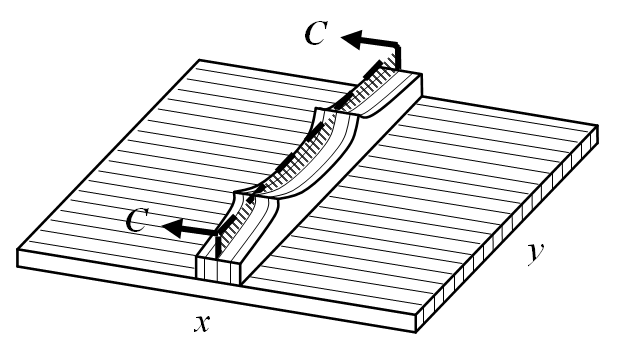
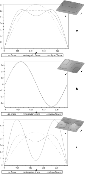
In order to perform the analysis and derive the modeshapes (eignenvectors) of the system, a computer algebra system was used (Maple). Maple is mathematical software package produced by Maplesoft which solves analytical equations such as those stipulated above. Modeshapes for the brace with a scalloped brace are compared to those of the plate alone and those of a plate with a rectangular brace. The effects of the brace shape can then be observed. In order to get a good understanding of the effect on modeshapes, 2D plots are given at three different cross sections (slices) of the plate along two directions. These can be observed in Fig. 3 to Fig. 8. Each 2D plot contains the corresponding 3D modeshape in the top right corner for reference.
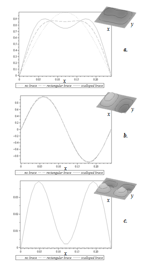
a. 1 × 1, b. 2 × 1, c. 1 × 2


a. 1 × 1, b. 2 × 1, c. 1 × 2.
a. 1 × 1, b. 2 × 1, c. 1 × 2.
Previous studies have shown that locally stiffening a plate increases certain frequencies while having very little effect on others. The reasons for this can be directly observed from the modeshapes.
3. 4. Discussion
From Fig. 4a and Fig. 6a and c, it is clear that locally stiffening the plate with a brace reduces the maximum amplitude possible for its vibration. This implies that frequencies associated with these modeshapes will increase. However, from Fig. 4a and Fig. 6a, it can be observed that scalloping the brace has very little impact compared to the simple rectangular brace on the average modeshape amplitude. This follows since the base thickness of the scalloped brace is very similar to that of the rectangular brace and since the maximum amplitude of the first modeshape occurs at the centre of the brace, the effect of both braces is similar.
The flattening of the modshape visible in Fig. 4a and Fig. 6a is to be expected and occurs because the brace is finite in width and is located at the center of this fundamental modeshape. It is interesting to note that although the scalloped brace flattens out the center portion of the modeshape more than it does for the rectangular brace, the amplitude of the modeshape seems to be compensated in the portions of the modeshape lying outside of the braced region. This helps explains why the fundamental frequency is less affected by the scalloped peaks than higher frequencies (Dumond and Baddour, 2012).
Conversely, observing the third modeshape in Fig. 6c, it can be seen that scalloping the brace has a significant effect on the maximum possible amplitude. This is because the peaks of the scalloped brace were designed to occur directly in the location of the maximum amplitude of this modeshape. Therefore this region is locally significantly stiffer with the scalloped brace versus the rectangular brace.
Furthermore, it can be observed from Fig. 4b and Fig. 6b that there is very little effect from either brace since the braces are positioned along the nodal line of the second modeshape.
Finally, Fig. 7 and Fig. 8 show the first three modeshapes along the brace in the y-direction, and it can be seen that the scalloped shape brace has the same effects as discussed previously. Once again, the scalloped shape has a much larger effect on the third modeshape, as seen in Fig. 8c, than it does on the first modeshape of Fig. 8a when compared to the rectangular brace.
Clearly this particular brace was designed to have the most significant effect on the third modeshape since the scalloped peaks occur exactly at the point of maximum amplitude for this modeshape. Looking at other modehsapes, it could easily be seen that if a maximum amplitude occurred near the region of the scalloped peak, the peak would have a larger effect on this modeshape than if it had a node at the same location. If the goal, then, is to significantly affect one particular frequency, the potential solution is to locally change the stiffness using a scalloped peak of extra material at the location of maximum amplitude of the frequency associated with that modeshape.
4. Conclusion
It thus becomes clear that by properly designing the shape of the braces on a soundboard and placing them in specific positions, an instrument maker has great control over the shape of modeshapes. By selecting some positions over others, it also allows some modeshapes to be modified without significantly affecting others.
Reducing the maximum amplitude of a modeshape increases the associated frequency. Reducing the maximum amplitude of a modeshape can be achieved by physically stiffening the system globally or locally. In this case, locally stiffening the system with a brace becomes much more interesting due to the requirement for the system to remain flexible overall. It also allows the modification of certain modeshapes (and therefore their associated frequencies) without significantly affecting others. This is extremely important when trying to control multiple frequencies associated with a set of modeshapes.
In the end, it may not be the modeshapes that control the sound produced by a musical instrument. However, by being able to locally control the stiffness of various regions of a soundboard and hence the maximum possible amplitudes for a given modeshape, it is possible to control the frequencies associated with these modeshapes. A desired increase in a certain natural frequency requires a simple stiffening of the areas associated with the maximum amplitudes of the related modeshape.
References
Bécache, E., Chaigne, A., Derveaux, G., Joly, P. (2005). Numerical simulation of a guitar. Computers & Structures, 83, 107–126. View Article
Bretos, J., Santamari´a, C., Moral, J.A. (1999). Vibrational patterns and frequency responses of the free plates and box of a violin obtained by finite element analysis. Journal of the Acoustical Society of America, 105, 1942. View Article
Brooke, M., Richardson, B.E. (1993). Mechanical vibrations and radiation fields of guitars. Journal of the Acoustical Society of America, 94, 1806. View Article
Chaigne, A. (1999). Recent advances in vibration and radiation of musical instruments. Flow, Turbulence and Combustion, 61, 31–34. View Article
Curtu, I., Stanciu, M.D., Cretu, N.C., Rosca, C.I. (2009). Modal analysis of different types of classical guitar bodies. Proceedings of the 10th WSEAS International Conference on Acoustics & Music: Theory & Applications, AMTA'09. World Scientific and Engineering Academy and Society (WSEAS), Stevens Point, Wisconsin, USA, pp. 30–35. View Article
Dumond, P., Baddour, N. (2012). Effects of using scalloped shape braces on the natural frequencies of a brace-soundboard system. Applied Acoustics, 73, 1168–1173. View Article
Elejabarrieta, M.J., Ezcurra, A., Santamaría, C. (2001). Vibrational behaviour of the guitar soundboard analysed by the finite element method. Acta Acustica united with Acustica, 87, 128–136. View Article
Elejabarrieta, M.J., Ezcurra, A., Santamari´a, C. (2000). Evolution of the vibrational behavior of a guitar soundboard along successive construction phases by means of the modal analysis technique. Journal of the Acoustical Society of America, 108, 369. View Article
Fletcher, N.H., Rossing, T.D. (1998). The Physics of Musical Instruments. 2nd Edition. Springer. View Article
Forest Products Labratory (US) (1999). Wood Handbook: Wood as an Engineering Material. U.S. Department of Agriculture, Forest Service. View Article
French, R.M. (2008). Engineering the Guitar: Theory and Practice. 1st Edition. Springer.
Hutchins, C., Voskuil, D. (1993). Mode tuning for the violin maker. CAS Journal II, 2, 5–9. View Article
Knott, G.A., Shin, Y.S., Chargin, M. (1989). A modal analysis of the violin. Finite Elements in Analysis and Design, 5, 269–279. View Article
Lawther, R. (2007). Assessing how changes to a structure can create gaps in the natural frequency spectrum. International Journal of Solids and Structures, 44, 614–635. View Article
Meirovitch, L. (1996). Principles and Techniques of Vibrations. Prentice Hall.
Natelson, J., Cumpiano, W. (1994). Guitarmaking: Tradition and Technology: A Complete Reference for the Design & Construction of the Steel-String Folk Guitar & the Classical Guitar. Chronicle Books.
Okuda, A., Ono, T. (2008). Bracing effect in a guitar top board by vibration experiment and modal analysis. Acoustical Science and Technology, 29, 103–105. View Article
Richardson, B.E. (1999). Experimental and theoretical studies of the modes of stringed instruments and their relevance for quality control of instrument manufacture. Journal of the Acoustical Society of America, 105, 1124. View Article
Siminoff, R.H. (2002). The Luthier's Handbook: A Guide to Building Great Tone in Acoustic Stringed Instruments. Hal Leonard.
Sumi, T., Ono, T. (2008). Classical guitar top board design by finite element method modal analysis based on acoustic measurements of guitars of different quality. Acoustical Science and Technology, 29, 381–383. View Article
Timoshenko, S.P., Kreiger, S.W. (1964). Theory of Plates and Shells. McGraw-Hill Higher Education.