International Journal of Mechanical Engineering and Mechatronics (IJMEM)
ISSN: 1929-2724

Volume 1, Issue 2 Year 2012 - Pages 72-79
DOI: 10.11159/ijmem.2012.009
Experimental Investigation of Dynamic Force on The Performance of Wet Snow Shedding
Reham M.H. Hefny, László E. Kollár, Masoud Farzaneh
NSERC/Hydro-Quebec/UQAC Industrial Chair on Atmospheric Icing of Power Network Equipment (CIGELE) and Canada Research Chair on Engineering of Power Network Atmospheric Icing (INGIVRE), UQAC
555 boulevard de l'Université, Chicoutimi, Québec, Canada
reham-mahmoud.hefny1@uqac.ca; laszlo_kollar@uqac.ca; masoud_farzaneh@uqac.ca
Abstract - Wet snow can create serious electrical and mechanical problems to power transmission networks due to its high adherence to materials. In this study, both adherence of wet snow to cables and wet snow shedding following the application of periodic loads were investigated in small-scale experiments. Wet snow was obtained from fresh dry snow collected from the top layer of snow accumulated outdoors. The collected dry snow was exposed to warm air for periods of time long enough to obtain the desired liquid water content (LWC) values. Wet snow sleeves were manually prepared after being compressed around the cable. The room temperature, snow sleeve length, cable diameter, and cable length were kept constant for each experiment. Dynamic load on the cable was simulated by a periodic excitation applied at one end of the cable, while the other end was fixed. Since fading adhesion is a condition for snow shedding, and since LWC is a critical factor influencing adhesion, the effects of excitation frequency and amplitude were investigated for different LWC values. LWC was examined for values from 10 to 40%. When free water began to increase, snow at this stage was wet and it adhered stronger to the cable than low LWC, where there is no enough water to stick on the cable or high LWC where snow is transparent. The LWC range was found experimentally between 20 to 30% (Hefny R. et al., 2009). Different snow shedding scenarios were studied, for which the shedding sequence and acceleration were observed at the excitation point, also cable tension at the fixed end and vertical displacement at the mid-point of the span were measured.
Keywords: Wet Snow, Shedding, Periodic Load, LWC, Adhesion.
© Copyright 2012 Authors - This is an Open Access article published under the Creative Commons Attribution License terms. Unrestricted use, distribution, and reproduction in any medium are permitted, provided the original work is properly cited.
1. Introduction
Dry snow accretion occurs at sub-zero air temperature, and wind speed less than 2 m/s. Its density is too low; it does not exceed 0.1 g/cm3. Furthermore, dry snow adhesive force is small; it rarely gives rise to extreme loads. However, dry snow cylindrical sleeve can form and shed spontaneously, giving dynamic vibration (Sakamoto, 2000). Whereas wet snow accretion occurs at temperature above freezing point, its density spans a range from 0.1 to 0.95 g/cm3. Wet snow accretion can form a cylindrical sleeve which cannot shed easily by wind because of its greater adhesive strength (Sakamoto, 2000).
Snow shedding is the name given to the physical phenomenon that occurs when the accreted snow suddenly drops off of the cables, either naturally or as a result of some form of intervention. The study of wet snow shedding from structures is important since snow shedding from one span causes imbalance between adjacent spans and may damage transmission line elements. Observations of natural wet snow shedding from a cable are rare and not well documented. Shedding occurs following an increase in the liquid water content (LWC) which is governed by the thermal equilibrium within the snow sleeve. Reported LWC values at shedding occurrence range between 20% and 40% in some studies (Admirat et al., 1988, Farzaneh, 2008), whereas they were observed to range between 35% and 50% in other ones (Roberge, 2006). Increase in LWC is mainly due to convective exchanges which control melting, and related to wind speed, air temperature or electric current (Farzaneh, 2008).
Consideration of snow shedding problems is very important in determining the alignment of the conductors, the type of towers and the configurations of spans. The shedding involves some danger, because it causes unbalanced load on the line from the point of view of line design it is essential to know the duration of snow staying on the cable, and understanding the snow propagation phenomena.
Flashover happened between phases or between shield wire and phase conductor, due to unequal sag increase between spans and phases of line (Sakamoto, 2000). A more frequent problem arises when the load is suddenly released. The conductor springs upwards and if the horizontal spacing between phase conductors is small, flashover between conductors may happen (Morgan and Swift, 1964).? As an example, when there is a conductor of 2 phases, and a heavy load remains on the top-phase conductor, while the bottom-phase conductor snow has fallen. The second hazard is conductor jump arising from the sudden release of snow from conductors; this can cause them to rise to heights which exceed the normal spacing between both conductors (Morgan and Swift, 1964).
In addition snow shedding generates strong conductor motion, which applies transient dynamic forces to the towers, and causes conductor swing toward each other, these dynamic forces can cause cascading of the towers, resulting in heavy damage to the line (Morgan and Swift, 1964). Impulse loads due to sudden snow shedding are another source of trouble in power networks. The dynamic effect of snow shedding on transmission lines creates two major categories of concern: electrical and mechanical. A lack of clearance between adjacent cables, cables and towers, and cables and the ground are the main electrical concerns. Mechanical concerns include the impact of suspension strings on towers, which may result in broken insulators. Snow shedding may also cause mechanical problems with excessive tensions generated in the cables and, eventually, large unbalanced loads on towers. Anti-icing and de-icing methods should be investigated to reduce these damages and to improve the mechanical characteristics of line components.
Wet snow sleeves shed naturally in some hours after their accumulation. Heating effects like Joule heating and solar radiation increases LWC of snow accretions: When snow sleeve loses its cohesion it shed naturally under the effect of gravity and wind. In general, it has been considered that snow accretion on overhead power lines occurs only when wet snowflakes adhere to wires at surface temperatures slightly above freezing. Sakamoto (2000) suggested that, in practice, the phenomenon of snow accretion may customarily be experienced under a relatively wide range of combinations of meteorological parameters. The observation records show that the snow accretion on overhead wires may occur at air temperature as low as -7°C. The consequences of atmospheric icing of overhead power lines are extremely important in terms of human life security, material damage, and reliability of electrical transmission lines. One of the major consequences is galloping of cables in high wind conditions. Galloping and other dynamic loads result in line component fatigue and damage.
Shedding may be preceded by two types of creep, the first type being caused by the effect of gravity, wind, temperature, and solar radiation (Roberge, 2006), whereas the second type being due to the inclination of the cable more? than 30-40° (Admirat et MacCagnan, 1985). According to Guilbeault's observation reported in (Roberge, 2006), snow sheds in a random and partial manner on phase conductors, whereas on overhead ground wires it sheds in an unzipping manner, which causes large oscillations. Snow may also shed in mixed mode, which means random and unzipping shedding together.
Wind tunnel experiments have shown that snow shedding is a random process. On short cable sections wet snow sheds suddenly or partially in small segments (Sakamoto et al., 2005). Shedding was also observed in a cold room at CIGELE laboratories. It was initiated at one end along the cable and progressed continuously at a measurable speed (Roberge, 2006). All of these experiments were carried out with cable-snow structures in their static equilibrium.
The aims of the present study were undertaken to predict snow shedding from cables due to dynamic effects, such as those that may result from the effect of wind or other external loads or from load imbalances due to propagating snow shedding on an adjacent span. The effects of excitation amplitude and frequency, snow LWC, and thickness of snow sleeve on the snow shedding process were studied experimentally.
2. Experimental Procedure
2.1. Equipment and Facilities
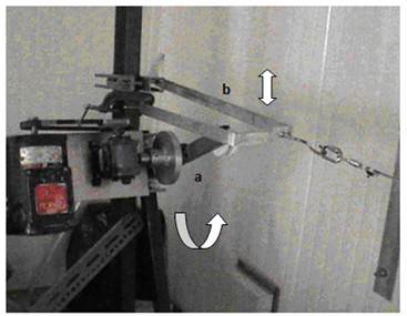
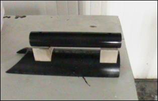
The experimental setup was installed in a cold room at the CIGELE icing precipitation simulation laboratory. The air temperature in this chamber was controlled and could reach -20?C, but in the present experiments the room temperature was set at 1?C, which is typical of wet snow accumulation on overhead cables. The experimental setup consisted of one fixed support, another movable one, and a flexible stainless steel cable (RR-W-410D301/302, 4.14-m long and 4.1 mm-diameter) mounted between these supports and connected to a load cell at the fixed end. The periodic load was provided by using a motor connected to the movable cable end, as shown in Fig. 1. The bar (a), connected to the axis of the motor, was moving in a circular trajectory. At each cycle it raised the horizontal bar (b) which was connected to the cable, and then let it fall causing a mechanical impact.
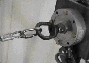
Horizontal component of the stainless steel cable end-tension was measured using universal pancake-load cell manufactured by FUTEK (model: LCF 450) (Fig.2a). This model used metal foil strain gauge technology (Asch, 1999). The load cell was designed for both tension and compression applications and had a capacity of 2224 N (500 lbf). It has a rated output of 2 mV/V nominal, a nonlinearity of ?0.1% of the rated output, an operating temperature of -50?C to 93?C, and deflection of 0.05 mm to 0.13 mm nominal. One load cell was installed to the cable. The bridge excitation of 10 VDC for the load cell was provided by a signal conditioner amplifier manufactured also by FUTEK (model: CSG110). It has a built-in regulated bridge excitation source that requires a power supply at the range of 12 to 24VDC @ 100 mA. It provides a voltage output of ?10 VDC at ?2 mV/V. The signal conditioner was installed outside of the refrigerated room.
An accelerometer to measure the acceleration is mounted near the movable cable end. The acceleration is measured by an ICP quartz force sensor designed by PCB Piezoelectronics (model: W352C04), as shown in Fig. 2(b). The analogue to digital conversion data acquisition is provided by Data Translation model DT9804. The measurement application software called DT Measure Foundry is used to acquire acceleration and tension data. Two high speed digital cameras are used to capture the cable mid-span and suspension point displacement.
Concerning, the best choice of the mounting method of the accelerometer
to the cable, the most important consideration is the effect the mounting
technique has on the high frequency performance of the accelerometer. Adhesive
mount was chosen from six mounting techniques for these current tests. This
adhesive mount is often used for temporary installation, or when
the test objects surface cannot be prepared for stud mounting. Direct adhesives
like two-part epoxies or quick bonding gels may provide a more permanent
installation. There were two methods using this adhesive mount, the adhesive
mounting base or the direct adhesive mount. The adhesive mounting base was used
in this current study, where it involved attaching a base to the test
structure, then securing the sensor to the base. The importance of this base
was that it manufactured of hard coated aluminium, which provided electrical
isolation to eliminate ground loops and reduce electrical interference that may
propagate from the surface of the test object (Fig.2b).
2. 2. Procedure and Sample Preparation
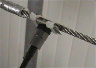
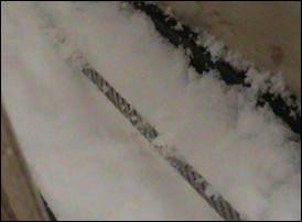
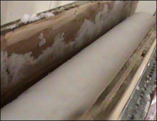
Wet snow sleeve molding: Fresh dry snow was used to prepare the wet snow in the climate room. The dry snow was collected from the top layer of snow banks outside the campus. The LWC of the snow approached that of precipitating wet snow after being exposed to warmer air for a period from 1 to 3 hrs. This method produces wet snow with homogenous LWC based on the recommendations of (Sakamoto 2000, 2005) and on the experiments of (Roberge, 2006). The wet snow was laid in a semi-cylindrical mold and compacted evenly in layers. Once the bottom half of the sleeve was formed below the cable (Fig. 3.a), the top half of the sleeve was also made of compacted layers using a semi-cylindrical tool (Fig. 3.b). The length of snow sleeve used was 2 m. Since two molds of different diameters were used, the fabricated snow sleeve had a uniform diameter of 9.8 or 5.1 cm after mold removal. Fig. 3(a and c) illustrates how the sleeve was molded.
 (a)
(a)
 (b)
(b)
 (c)
(c)
LWC and Density Measurements: LWC was calculated by using a Decagon model EC-5 moisture sensor. This sensor provides a reading in voltage (v), which is based on the dielectric constant of the medium. This voltage is converted into volumetric water content using a calibration curve, and the LWC (by mass) is obtained by dividing the volumetric water content by the snow density, from which the volumetric water content (VWC) is calculated by:
|
VWC = (voltage . 0.06) - 23 |
(1) |
This data collection system is a best way for measuring different readings for LWC, as it has five different ports. By fixing the probes inside these ports, the device may save the data, which can be recorded on the concerned program.
In the dynamic test, four probes were used. Two were placed at each end of the snow sleeve, and the LWC was obtained by calculating the average of these voltages. The average error in these measurements was evaluated around ? 4%. The snow density was determined by dividing the snow mass by the volume of a container where a snow sample was collected. The mass was measured using a digital balance.
3. Results and Discussion
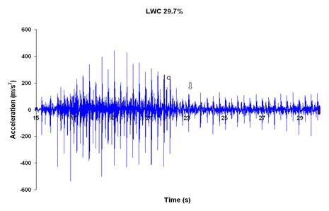
This section shows a typical dynamic impact characteristics measured by the ICP accelerometer sensor during a test. Recording of data was started at t = 0 s; however, the periodic impact generator was actuated only after some seconds later. The full spectrum of the acceleration measurement show a periodic high impact, which was repeated for around 10 cycles. Between each impact and the successive one there were a couple of low oscillations peaks. The results of dynamic tests are presented here, where the periodic impact (with measured acceleration time history) was applied as an input parameter. The snow-shedding process and the cable jump at mid-span were observed, simultaneously, also the cable tension was measured using the load cell.
The presented figures were prepared from the results of more than 120 tests carried out to observe and verify the characteristics of the measured parameters. Four parameters were varied during the experiments, namely, (i) LWC with values ranging from 10 to 40%; (ii) sleeve with two outer diameters: 51 mm (small sleeve) and 98 mm (large sleeve); (iii) excitation amplitude with 155, 170, and 185 mm, which called low, middle and high amplitude, respectively. Its amplitude was being defined as the distance between the main bar center and the small disk (Fig.1b); and (iv) motor speed at levels ranging from 2 to 8 (i.e. 20% to 80% of the motor base speed) controlling the period of excitation corresponding to the time between two impacts. Ranges for this period, as measured for motor speed level 2, were provided in Table 1. Values within these ranges differ depending on the excitation amplitude.? Table 1 shows that the period of excitation increases with increasing LWC and sleeve diameter. Once these parameters enlarged, the weight of snow increased, making it more difficult for the set-up to raise a cable with a heavier sleeve. When motor speed level increased, the period decreased. Moreover, once a section of the snow sleeve sheds, the load becomes lighter and the period is further decreased. It would be difficult to compare different cases for high motor speed levels because the rate of shedding affects the results.
Table 1. Ranges for period of vibration for different LWCs and sleeve diameter.
|
Large sleeve |
Small sleeve |
|||
|
LWC |
Low |
High |
Low |
High |
|
Time (s) |
1.74-2.9 |
2.16-3.29 |
0.98-1.74 |
1.34-2.37 |
3.1. Large Snow Sleeve and Middle Excitation Amplitude
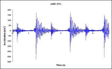
Snow shedding at low (less than 15%) or high (more than 35%) LWC usually happens by propagation, in an unzipping way from the excited end towards fixed end of the cable, which is followed partially (in small sections at distinct locations). Some parts of snow shed at low motor speed (level 2) in pieces of about 35 cm, then after waiting around 60 cycles with no more shedding, the motor speed was increased to speed level 3 and snow shed. The highest peak acceleration on impact found to range from 200 to 300 m/s2 (Fig. 4.a) at motor speed level-2? and from 300 to 400 m/s2 at speed level -3 (Fig. 5). The time between two impacts decreased from 2.9 s to 1.2 s. As snow shed, the acceleration and tension changed even at the same motor speed because the cable became unloaded. The acceleration peak at shedding was 380 m/s2, but after shedding it decreased to about 200 m/s2 at speed level-3 (Fig. 4.b).
 (a)
(a)
 (b)
(b)
For LWC ranges between 15 to 18 %, it was noticed that snow was more resistant on the cable than in the former case, as it would not shed easily at speeds 2 or 3, except for one or two short sections close to the excitation point. Some snow sections would stay until motor speed increase up to level-4, and then they shed partially. The acceleration peak at speed level-4 at shedding is 425 m/s2.
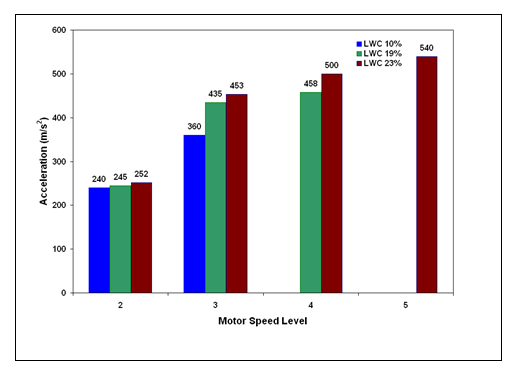
For LWC ranges from 18 to 20%, low motor speed affected only some small sections of the snow sleeve, whereas the main shedding process proceeded in an unzipping way at speed level-4. Snow blocks slide on the cable towards each other without shedding indicating that cohesion keeps snow particles together even if adhesion between the snow and the cable had vanished. The acceleration peak at speed level-4 was 458 m/s2. However, snow was most resistant when LWC was in the range of 20 to 30%. There was no shedding at the low motor speed although there were several cracks. Then, increasing motor speed to level-3 caused the snow to shed in an unzipping way from the excitation side. Snow sections slid toward mid-span with no additional shedding, and stayed on the cable until motor speed increase to level-5 causing the remaining sections to shed suddenly. At this point, the acceleration peak was 540 m/s2.
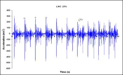
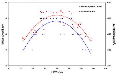
Figure 5 shows how snow adherence onto the cable increases with increasing LWC up to about 30%. For LWC ranging from 10% to 15% snow sheds at motor speed level-3, with acceleration peak of 380 m/s2 at shedding. For LWC between 15% and 20%, the snow stays until speed level-4 is reached. The average acceleration peak at shedding is 458 m/s2. For LWC between 20% and 30%, snow stays until level-5 speed with peak acceleration of about 540 m/s2 at shedding. Further increase in LWC weakens snow adhesion and when LWC reaches 35%, snow sheds for motor speed as low as level-3. Figure 6 summarizes the relation between LWC and motor speed level or acceleration at shedding. Snow sheds after the application of the most severe excitation when the LWC is ranging from 20 to 30% where the strongest adhesion strength was measured using MTS machine (Hefny R. et al. 2009).
The horizontal component of the cable-end tension generated by the dynamic load is measured using the load cell. Since the vertical tension is very small compared to the horizontal one, it is not measured. It may be observed that the tension slightly increased with increasing motor speed, but decreased after snow shedding since the load was removed from the cable. The cable tension in the bare cable was 218.5 N, which increased to 250 N after adding the snow load. The LWC increase had no considerable effect on cable tension.
3.2. Large Snow Sleeve and Low Excitation Amplitude
Snow stays more time on the cable by using low excitation amplitude since the small amplitude caused small impacts, even by changing motor speed up to level-8 either at low or high LWC. In the experiments, when LWC was 35%, the entire snow sleeve stayed on the cable at motor speed levels 2 and 3. Then the major part of the snow shed by unzipping way at speed level-5. After further increasing the motor speed up to level- 6, there is no shedding but snow blocks slide towards mid-span. Then, the rest sheds at speed level-8 followed by a drop in the acceleration peak (Fig. 7.a). For small excitation amplitude the set-up needs less energy to raise the suspension-point, thus there is faster rotation than large sleeve. Fig.7(b) shows how the peak acceleration increases by increasing motor speed.
Shedding happened at speed level-8 as impact is around 380m/s2; this is small comparing to the impact at shedding using middle amplitude (cf.Figs.4b, 7b). This impact at speed level-8 using low amplitude corresponded to the impact at speed level-3 for low LWC-middle amplitude (cf.Figs.5,7b).
 (a)
(a)
 (b)
(b)
3.3. Large Snow Sleeve and High Excitation Amplitude
When the excitation amplitude was high, snow shed easily, even for snow with the strong adhesion (middle range of LWC). Some sections of length around 35 cm shed at speed level-2, but the rest shed at speed level-3. If motor speed level-4 was applied from the beginning of the test, wet snow might shed immediately. Acceleration peak at shedding was 350 m/s2. A similar shedding scenario (motor speed levels of 2 and 3) happened at high LWC values (Fig.8), but with fast shedding at speed level-3. Concerning middle range of LWC, snow shed at acceleration peak 280m/s2 at motor speed-level-3. Table 2 showed the relation between different excitation amplitudes and corresponding acceleration peaks for different LWC including sections (3.1, 3.2, 3.3). For middle LWC and middle excitation amplitude (170mm) snow may shed at 540m/s2 compared with small acceleration peak, i.e; 355 m/s2 at high excitation amplitude. This small peak in turn seems close to low LWC at middle excitation amplitude. Whereas using low excitation amplitude results in a very low acceleration peak at shedding although it reaches motor speed level-8 (Table 2)
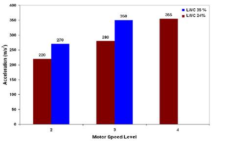
Table 2. Relation between excitation amplitude and acceleration at shedding for different LWC (Sleeve 98 mm
|
Excitation amplitude (mm) |
170 |
185 |
155 |
|||
|
LWC |
10 |
19 |
23 |
24 |
35 |
29 |
|
Accelerations (m/s2) |
360 |
458 |
540 |
335 |
350 |
380 |
3.4. Small Snow Sleeve and Middle Excitation Amplitude
Changing the snow diameter slightly affects the snow shedding sequence. However, it affects significantly the acceleration amplitude and the time between two acceleration peaks. The acceleration peak values are lower for small sleeve than for a large sleeve since a small sleeve has small weight thus being easier to move. Changing the sleeve decreases the acceleration peak by 50% for level-2 speed (cf. Figs. 5 and 9), but it is decreased to a lower extent for level-3 speed (cf. Figs. 4.b and 9).? Snow stays for low LWC up to level-3 speed, whereas for middle LWC it stays up to level-4 speed, where the acceleration peak at shedding is around 320 m/s2. It should be mentioned that the cable tension for small sleeve is lower than cable tension for large sleeve because of the small load, 225 N as compared to 250 N. Also, the shed sections are small for this small sleeve, they are 15 cm long compared to 35 cm for the large one.
3.5. Small Snow Sleeve and Low Excitation Amplitude
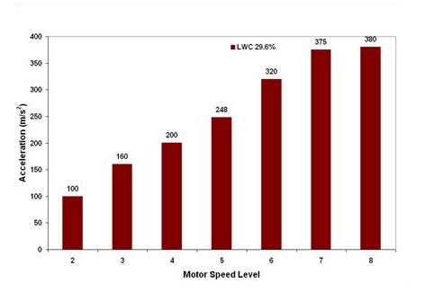
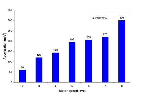
In case of a small snow sleeve, the shedding process was similar to that of a large sleeve and low-excitation amplitude. However, low acceleration peaks and low tensions were obtained, and the period of vibration was increased because snow load was small, i.e., it is easier for the system to raise the sleeve efficiently in small time. The acceleration peak at shedding was 300 m/s2 at motor speed level-8 comparing to 380 m/s2 for large sleeve (cf. Figs. 7 and 10). The acceleration peaks increased from 60 m/s2 at speed level-2 to 300 m/s2 at speed-level-8(Fig.10). Where this acceleration peak found at speed level-2 is low compared with large sleeve impact, which is around 100 m/s2 for the same speed level.
3.6. Small Snow Sleeve and High Excitation Amplitude
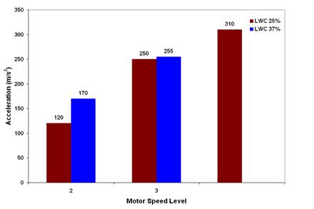
It was remarkable that for high and low LWC values, snow shed quickly at low motor speed level (Fig.11). Whereas for strong adhesion (middle range of LWC) snow might stay more up to speed level-4, whenever it shed rapidly. Sliding action became visible at speed levels-2 and-3, which confirms that adhesion can vanish early, while cohesion between snow particles is still high, even if the sleeve diameter was small and LWC is high. Acceleration peak at shedding was 380 m/s2. Table 3 showed the relation between different excitation amplitudes and corresponding acceleration peaks for different LWC including sections (3.4, 3.5, 3.6). It seemed that the acceleration peak for low excitation amplitude and middle LWC is close to the peak for? middle excitation amplitude, although for the former, snow shed at motor speed level-4, whereas for the latest snow shed at motor speed level-8. This case happened since the sleeve is small, thus there is no high impact for raising it up (see Table3). Table 3 demonstrates the difference between high LWC at middle excitation amplitude and at high excitation amplitude, where for the first case the impact is lower than the second one because snow load is forced and may hit the cable strongly.
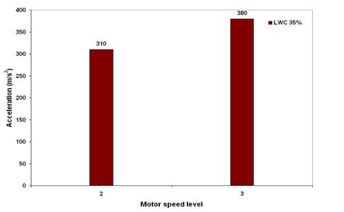
Table 3. Relation between excitation amplitude and
acceleration for different LWC
(Sleeve 51 mm).
|
Excitation amplitude (mm) |
170 |
185 |
155 |
|
|
LCW (%) |
LCW (%) |
LCW (%) |
||
|
25 |
37 |
35 |
29 |
|
|
Accelerations (m/s2) |
310 |
255 |
380 |
300 |
4. Conclusion
Small scale experiments were performed to simulate snow shedding due to a periodic load including an impact in each period. The following conclusions may be drawn from the obtained results:
- 1. Snow shedding happens in an unzipping way, from the excited toward the fixed end for low excitation frequencies, low motor speed levels or small impacts. However, it sheds partially or by mixed shedding at high frequencies. This sequence is generally the same for a large sleeve (D= 98 mm) and a small one (D= 51mm), but the size of the shedding sections are different, around 35 cm and 15 cm, respectively.
- 2. For middle values of LWC and for middle excitation amplitude, snow sheds at high excitation frequencies. For low and high LWC, however, snow stays only at low excitation frequencies.
- 3. At high excitation amplitude, snow sheds easily with a very fast sequence whereas at low amplitudes snow will stay on the cable for a longer time.
- 4. Cohesion force within the snow is greater than its adhesion strength to the cable. At high excitation frequencies when snow sheds partially, snow sections are observed sliding towards mid-span resulting from vanished adhesion while cohesion keeps them together.
- 5. The acceleration peak increases as the period of vibration decreases, with sleeve diameter.
- 6. Changing snow sleeve diameter does not affect the sequence of snow shedding, but it rather changes the rate of shedding at each motor speed level. In addition, the shedding pieces decrease using the small sleeve, and also the acceleration peaks decreased for the case of small sleeve.
Acknowledgements
This work was carried out within the framework of the NSERC/Hydro-Quebec/UQAC Industrial Chair on Atmospheric Icing of Power Network Equipment (CIGELE) and the Canada Research Chair on Engineering of power Network Atmospheric Icing (INGIVRE) at Université du Québec à Chicoutimi. The authors would like to thank the CIGELE partners (Hydro-Québec, Hydro One, Réseau Transport d'électricité (RTE), électricité de France (EDF), Alcan Cable, K-Line Insulators, Tyco Electronics, Dual-ADE, and FUQAC) whose financial support made this research possible.
References
Admirat P., MacCagnan M. (1985). " Observations de Neige Collante sur Les Lignes Electriques ", 41p.
Admirat P., MacCagnan M., DeGoncourt B. (1988). Influence of Joule Effect and of Climatic Conditions on Liquid Water Content of Snow Accreted on Conductors "Proceedings of the 4th International Workshop on Atmospheric Icing of Structures," France, 367-371.
Asch, G.(1999), Les capteurs en instrumentation industrielle, 5e ?dition, Paris, France. View Article
Farzaneh M.(2008) "Atmospheric Icing of Speed Networks", Springer, Berlin, 381 p.
Hefny R.,Kollar L.,Farzaneh M.,Peyrard C.(2009). Adhesion of Wet Snow to Different Cable Surfaces Conductors "Proceedings of The 13th International Workshop on Atmospheric Icing of Structures," Suisse, Poster session, 7p.
Morgan, V. T, Swift, D. A, (1964), Jump height of overhead line conductors after the sudden release of ice loads, Proceedings of IEEE ; 111 (10), 936-946. View Article
Roberge, M. (2006). "Study of Wet Snow Shedding from an Overhead Cable," M. Eng. Thesis, McGill University, Canada. View Article
Sakamoto Y.(2000). Snow Accretion on Overhead Wires "Philosophical Transactions of the Royal Society," 2941-2970. View Article
Sakamoto Y., Tachizak S., Sudo N.(2005). Snow Accretion on Overhead Wires "Proceedings of the 6th International Workshop on Atmospheric Icing of Structures," Montreal, Canada, 3-9.