International Journal of Mechanical Engineering and Mechatronics (IJMEM)
ISSN: 1929-2724

Volume 2 - Year 2014 - Pages 43-50
DOI: 10.11159/ijmem.2014.005
Surface Finishing of Micro-channels Using Low Kinetic Energy Abrasives
Reza Haj Mohammad Jafar¹, Jan K. Spelt¹, Marcello Papini²
¹University of Toronto, Department of Mechanical & Industrial Engineering
5 King's College Road, Toronto, Ontario, Canada M5S 3G8
rezahmj@mie.utoronto.ca; spelt@mie.utoronto.ca
²Ryerson University, Department of Mechanical and Industrial Engineering
350 Victoria Street, Toronto, ON, Canada M5B 2K3
mpapini@ryerson.ca
Abstract - Abrasive jet micro-machining (AJM) is a promising technique to machine micro-features in brittle and ductile materials. However, the roughness of micro-channels machined using AJM is generally greater than that from other methods of micro-machining such as wet etching. Previous investigators have suggested that the roughness of AJM surfaces can be reduced by post-blasting with abrasive particles at a low kinetic energy. This approach was investigated by measuring the roughness reduction of a reference unmasked channel in borosilicate glass as a function of post-blasting particle size, shape, velocity, dose, and impact angle. The roughness of the reference channel decreased up to 70% of its initial value after post-blasting. It was found that post-blasting with smaller particles ultimately resulted in smoother surface, but at the penalty of requiring a relatively high particle dose, and consequently a significantly increased channel depth before reaching the steady-state roughness. Hence, finishing with small particles until reaching the steady-state is not practical when a shallow channel is desired.
Keywords: Abrasive jet micro-machining, surface roughness, post-blasting, micro-fluidics, Glass.
© Copyright 2014 Authors - This is an Open Access article published under the Creative Commons Attribution License terms. Unrestricted use, distribution, and reproduction in any medium are permitted, provided the original work is properly cited.
Date Received: 2013-10-30
Date Accepted: 2014-02-23
Date Published: 2014-07-07
Nomenclature
- d: Stand-off distance
- Ra: Average roughness
- ec: Energy density at channel centerline
- t: Machining time
- E: Etch rate
- Uth: Kinetic energy threshold of cracking
- h: Channel depth
- V: Particle velocity
- L: Channel length
- Vs: Scanning speed
- m: Particle mass
 : Energy flux
 : Particle mass
flow rate
: Particle mass
flow rate
- μbw: Jet focus coefficient
- P: Pressure
- μq: Angle of attack
- r: Distance from jet center
 : Particle mass
flux
: Particle mass
flux
1. Introduction
Abrasive jet micro-machining (AJM) is a method of mechanical material removal in which an abrasive particle jet is directed towards a target surface to machine micro-features by erosion mechanism. AJM has been used to make micro-electro-mechanical devices such as electronic devices [1] and micro-fluidic components for capillary electrophoresis chips [2].
The roughness of micro-channels made using AJM can affect fluid flow phenomena in micro-fluidic applications. For example, it has been observed that increasing channel roughness lowers separation efficiency and electro-osmotic mobility, and increases solute dispersion in plug flow [3]. Surface roughness also plays a major role in micro-scale adhesion contact in MEMS [4], and since it scatters light, contributes to power attenuation in optoelectronics devices [5]. Therefore, it would be useful to be able to develop practical methods to reduce the roughness of the evolving features machined using AJM.
Slikkerveer et al. [6] studied the solid particle erosion of glass struck by hard, sharp particles. Making use of the lateral crack theory of Marshall et al. [7], they obtained the dimensions of impact craters to estimate the resulting roughness. Their model provided reasonable predictions of the roughness of borosilicate and soda-lime glass impacted by jets of alumina particles at normal incidence. It was concluded that the only important parameter affecting the roughness was the kinetic energy of the impinging particles. The effect of impact angle was not studied in their work. The accuracy of this model was investigated by Jafar et al. [8] who measured the dimensions of individual impact sites resulting from blasting aluminum oxide particles on a borosilicate glass. It was found that lateral crack initiation was better approximated as originating from the indentation depth rather than the bottom of the plastic zone. Accordingly, they modified the Slikkerveer's model [6] leading to a significant improvement in the estimations of erosion rate and roughness of channels machined with AJM in borosilicate glass. It was also shown that decreasing the nozzle inclination angle from 90° resulted in smoother channels and lower erosion rates, because of reducing the normal impact force which leads to removal of smaller craters from the target surface.
Wensink et al. [9] decreased the roughness of channels in borosilicate glass machined using two alumina powder sizes of 29 and 9 μm by about 40% by annealing the eroded borosilicate glass at 750°C. In contrast, a post-blast wet etching of AJM micro-channels in borosilicate glass with hydrofluoric acid produced a rougher surface, probably because of the opening of cracks generated by the AJM. Post-blasting the original channels (17μm deep) with 3 and 9 μm alumina decreased the roughness by about 25% while the depth of channels increased approximately 10 μm. Mineta et al. [10] examined the reduction of roughness due to post-blasting using a wet abrasive on a borosilicate glass (Pyrex™) substrate. Both the original and the post-blasted channels were machined using an aqueous abrasive slurry of 4 μm alumina, however the later were machined with a lower pressure so that a ductile-mode erosion was dominant, resulting in a roughness reduction of about 50%. Jafar et al. [11] post-blasted rough channels in borosilicate glass (Ra=5.0 μmm) with 50, 100, and 150 μmm sharp aluminum oxide particles at different pressures and impact angles. The roughness of the channels reduced down to 2.0 μmm after the smoothing process. It was observed that post-blasting at shallower angles was more efficient, probably due to the increased amount of edge chipping, which contributed to the enhanced removal of profile peaks, leaving a smoother surface. The impact force of postblasting particles in all the conditions investigated in Ref. [11] was above the cracking threshold of the borosilicate glass, resulting in brittle erosion mechanism in the posblasting process. Postblasting with spherical particles was not studied in their work.
The present work investigates the role of post-blasting particle shape, size, dose, velocity, and impact angle on the roughness reduction of AJM machined channels in borosilicate glass. The initial channels are smoother (Ra=1.3 μm) than those used in Ref. [11]. Moreover, unlike the blasting conditions used in Ref. [11], the kinetic energy of a fraction of the finishing particles is below the cracking threshold. Thus, the erosion mechanism is a combination of brittle and ductile erosion modes.
2. Experimental Procedures
The experiments were
conducted using an AccuFlo abrasive blaster from Comco Inc. (Burbank, CA, USA)
with a blasting nozzle having an inner diameter of 1.5 mm which was held
stationary at a nozzle-to-surface centerline stand-off distance of 10 mm. The
target material was 3 mm thick Borofloat® 33 borosilicate glass
(Schott Inc., NY, US) having a Young's modulus E=63
GPa, Poisson's ratio of υ=0.2, fracture toughness Kc=0.76
MPa![]() ,
and a Vickers hardness H=5.4 GPa. The glass plates were attached to a
computer-controlled stage and scanned below the stationary nozzle at scan
speeds, Vs, between 62 μm/s and 4 mm/s.
,
and a Vickers hardness H=5.4 GPa. The glass plates were attached to a
computer-controlled stage and scanned below the stationary nozzle at scan
speeds, Vs, between 62 μm/s and 4 mm/s.
To provide a baseline channel roughness from which various post-blasting scenarios could be evaluated, unmasked reference channels were machined at normal incidence (i.e. θ=90° in Figure 1), using 25 μm alumina particles at a scan speed of 5 mm/s and a pressure of 200 kPa. The average depth of three machined reference channels measured with an optical profilometer (Nanovea Inc., Irvine, CA) was 60 μm, with a standard deviation of 3.6 μm while the average width was approximately 3 mm. The measurements were made over three cross sections along the channel. Using an image analyzer (Clemex Technologies Inc., QC, Canada), the 25 μm alumina particles were found to have a mean circular diameter of 21.9 μm and an average aspect ratio of 1.67 (32,000 particles). Moreover, 241 particles were examined under the optical profilometer to measure the third dimension of the particles. The mean height was measured 14.2 μm. This indicates that the particles are of blocky shape rather than being flaky.
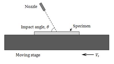
The reference channels were then post-blasted with alumina particles of three sizes (10, 17 and 25 μm) at a pressue of 100 kPa, and glass beads of 35 μm size at 400 kPa, and impact angles of 30º, 45º and 90º. Achieving erosion for angles shallower than 30º was impractical since the presence of a high-speed boundary layer on the target reduces the particle impact speed and angle, which can substantially decrease the erosion rate, particularly of small particles [12]. The particle velocity and average mass flow rate for each of the post-blasting conditions are given in Table 1. The average mass flow rate was determined by weighing the particles exiting the nozzle in 2 min. The particle velocities at the center of the jet were obtained using the model of Li et al. [13], which has been shown to give good estimates of particle velocities.
The roughness of a
post-blasted channel was expected to depend on the particle velocity, size,
density, and dose (particles striking per unit area per unit time). These
parameters can be conveniently combined into the energy flux; i.e. incident
energy per unit time arriving at a unit area, ![]() defined
as
defined
as
|
|
(1) |
where ![]() denotes
the particle mass flux and V represents the particle velocity (assumed
to be constant across the jet). An expression for the particle mass flux, φ(r),
at a given radius of a particle jet, r, was presented by Ghobeityet al.
[14] as
denotes
the particle mass flux and V represents the particle velocity (assumed
to be constant across the jet). An expression for the particle mass flux, φ(r),
at a given radius of a particle jet, r, was presented by Ghobeityet al.
[14] as
|
|
(2) |
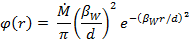
where ![]() is
the mass flow rate [kg/s] through the nozzle, d is the stand-off
distance and
is
the mass flow rate [kg/s] through the nozzle, d is the stand-off
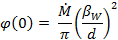
distance and ![]() represents
jet focus coefficient which is a dimensionless constant. Therefore, the mass
flux at the center of the stream (r=0), where roughness was measured,
simplifies to
represents
jet focus coefficient which is a dimensionless constant. Therefore, the mass
flux at the center of the stream (r=0), where roughness was measured,
simplifies to
|
|
(3) |
The energy density at the channel centerline, ![]() ,
is then obtained as the product of the energy flux at the centerline times the
duration of blasting over a unit length
,
is then obtained as the product of the energy flux at the centerline times the
duration of blasting over a unit length
|
|
(4) |

Burzynski and Papini [15] found βW =18 for 25 μm alumina particles blasted at 100 kPa. Since their results showed there is not a significant difference in βW for different particle sizes at a same condition, the same value (βW =18) is assumed to hold for 10 and 17 μm particles.
Table 1. Velocity and mass flow rate of impacting particles.
|
Particle material |
Particle size (μm) |
Size range(μm) |
Pressure (kPa) |
Particle velocity (m/s) |
Mass flow rate (g/min) |
|
Aluminum oxide |
25 |
8-53 |
200 |
130 |
6.4 |
|
25 |
8-53 |
100 |
96 |
5.8 |
|
|
17 |
3-35 |
100 |
113 |
5.7 |
|
|
10 |
2-20 |
100 |
140 |
5.1 |
|
|
Soda-lime glass |
35 |
7-60 |
400 |
182 |
16.2 |
The roughness along the centre-line of the channels was measured using the optical profilometer profilometer with a 0.1 μm step size and a cut-off length of 250 μm. The quoted roughness values represent the average of three repeat measurements, each over a scan length of 5 mm. The standard deviation of three measurements for all the transient and steady state roughnesses was less than 0.1 μm. The depth and the steady-state roughness (Ra) of the reference channels with scan speed of 5 mm/s were 60 μm and 1.3 μm, respectively.
The kinetic energy threshold of cracking, which is the minimum particle kinetic energy due to the surface-normal component of velocity at which the cracking initiates, is given by [9]
|
|
(5) |
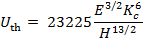
For borosilicate glass with the properties of Section 2, Uth=39 nJ.
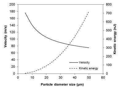
The alumina particles used in the experiments have a range of sizes (Table 1). Since the velocity of a particle depends on the size, there is a range of particle velocity and kinetic energy in an abrasive jet. Larger particles have a lower velocity and higher kinetic energy (Figure 2). Using the model of Li et al. [13], it was found that at 100 kPa and 10 mm from the nozzle exit the kinetic energy of the alumina particles with sizes less than 14 μm is lower than the Uth. Based on the particle size distribution provided by the manufacturer (Comco Inc.), the diameters of 10% of 25 μm alumina particles, 40% of 17 μm alumina particles, and 85% of 10 μm is less than 14 μm. Therefore, a fraction of alumina particles at each blasting condition had a kinetic energy lower than Uth and the erosion mechanism was a combination of brittle and ductile erosion modes.
3. Results and Discussion
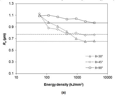
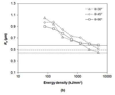
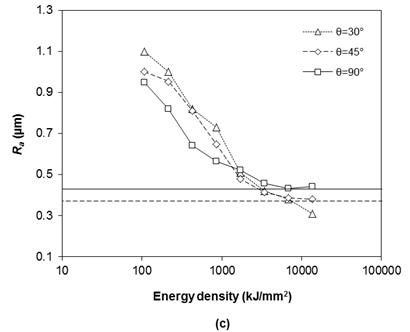
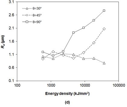
Figure 3 shows how the roughness changed with the energy density of post-blasted particles at various angles of attack. In each case, the starting roughness was that of the reference channel (1.3 μm). Also shown on each graph is the steady-state roughness achieved on an initially smooth glass surface eroded with the same particles used for post-blasting which determines the minimum achievable roughness in each post-blasting condition.
The required energy density to achieve a steady state roughness increased when post-blasting with smaller particles. For example, at P=100 kPa and θ=90º, the required energy density for 25, 17, and 10 μm particles was approximately 3.7, 5.0, and 6.9 MJ/mm-2, respectively (Figure 3a-c). This is because smaller particles have a greater probability of impacting near the bottom of existing craters, thus eroding both the peaks and valleys simultaneously. Larger particles, on the other hand, are less likely to reach valleys, and will thus preferentially erode peaks. Since the chipping resistance of peaks is less than that of valleys, the peaks are eroded at a higher rate, until a steady state is reached, while the crater wavelength remains constant.
Although the ultimate roughness is lower for lower impact angles under otherwise identical conditions, varying the impact angle of an alumina particle jet of a given size did not significantly change the surface roughness for a given energy density of alumina particles (Figs. 3a-c). Figure 3d shows that the glass beads increased the roughness when striking the surface at steep angles, probably because the impact force was high enough to make new, relatively large craters on the surface. For example, an extra 70 μm was removed from the reference channel when glass beads impacted at normal incidence and energy density of 36.9 MJ/mm-2. However at the shallowest impact angle (30º) the surface roughness reduced, due to preferential surface peak removal where almost no significant change in channel depth was observed. Due to the small difference between the hardness of the target and that of glass beads the steady state roughness was not established even after a large amount of particle energy density.
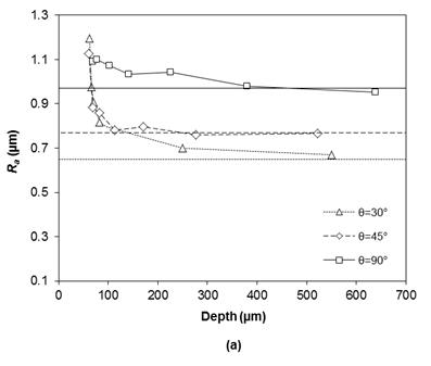
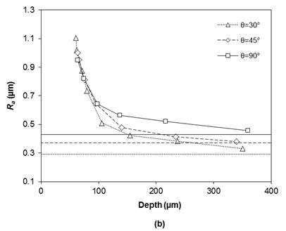
4. Machining Time
Post-blasting particles change the reference channel roughness as well as its depth. It is because probably every particle striking at the target removes a chip which causes an increase in the channel depth. The roughness variation of a channel against the depth variation is depicted in Figure 4 for 25 and 10 μm particles at P=100 kPa and θ=90º. The initial channel depth was 60 μm. In the early stage of the graph when not significant material is removed from the reference channel (maximum depth=100 μm in Figure 4b) the data for all angles lie on a single line. In this stage using larger particles seems to be reasonable because of their higher etch rate. After this stage the data for each impact angle starts separating to reach the corresponding steady state roughness. In this stage for a given depth shallower impact angle yields a lower surface roughness.
The results of experiments showed that postblasting with the particle jet of lowest kinetic energy resulted in the minimum surface roughness. However, on the other hand, the etch rate is proportional to the particle kinetic energy. It is thus of interest to consider whether it is better to simply use the smallest particles available to machine a channel, or whether it is better to instead initially blast with a larger particle (rapid etch rate), followed by a postblasting process with finer particles.
To assess the time required to machine a channel in a borosilicate glass, the dependence of channel depth on the particle mas was experimentally determined. Figure 5 presents the particle mass required to machine an unmasked channel with a length of 10 mm to a given depth in borosilicate glass for two machining conditions both at normal incidence.
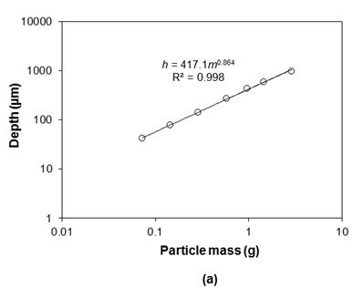
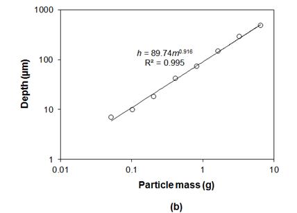
To machine a channel having a minimal roughness (and θ=90º) there were two methods of machining: (1) machining only with the smallest particles (10 μm), and (2) blasting with 25 μm followed by postblasting with 10 μm particles. To reach the steady state, the reference channels had to be posblasted with 10 μm particles at scanning speed of at least 125 μm/s (Figure 4b), in which case, the depth of the channels increased about 360 μm. Hence, if the method 2 is chosen, in the postblasting part at least 360 μm has to be removed with 10 μm particles, in order to get the same roughness as method 1.
The required time to machine a channel with a given length and depth of h using method 1 is obtained by the following relation
|
|
(6) |

where ![]() is the etch rate of the target when attacked by postblasting
particles for the given length. The time required to machine a channel with the
same length, depth and roughness using method 2 is
is the etch rate of the target when attacked by postblasting
particles for the given length. The time required to machine a channel with the
same length, depth and roughness using method 2 is
|
|
(7) |

where ![]() is the etch rate of the target when machined with original
particles for the given length, and
is the etch rate of the target when machined with original
particles for the given length, and![]() (
(![]() 360 μm in this case study).Obviously, as deeper channel are desired, the postblasting process is more practical and time efficient. For instance, machining a 10 mm long and 600 μm deep channel with method 1 takes more than four times longer than that using method 2.
360 μm in this case study).Obviously, as deeper channel are desired, the postblasting process is more practical and time efficient. For instance, machining a 10 mm long and 600 μm deep channel with method 1 takes more than four times longer than that using method 2.
5. Conclusion
It was found that a practical and effective method to reduce the surface roughness is post-blasting the original surface with a particle jet of lower kinetic energy. The effect of post-blasting particle size, shape, velocity, dose, and angle of attack on the resulting reduction of roughness of borosilicate glass was investigated. The roughness of the reference channels decreased up to 70% of its initial value after post-blasting. The post-blasting process with smaller particles ultimately resulted in smoother surface, but at the penalty of requiring a relatively high particle dose, and consequently a significantly increased channel depth, before reaching the steady-state roughness. Hence, finishing with small particles until reaching the steady-state is not practical when a shallow channel is desired.
References
[1] D. Park, M. Cho, H. Lee, W. Cho "Micro-grooving of glass using micro-abrasive jet machining" Journal of Materials Processing Technology, 146, 2004, 234–240. View Article
[2] S. Schlautmann, H. Wensink, R. Schasfoort, M. Elwenspoek, A. Van Den Berg "Powder-blasting technology as an alternative tool for microfabrication of capillary electrophoresis chips with integrated conductivity sensor" Journal of Micromechanics and Microengineering, 11, 2001, 386–389. View Article
[3] D. Solignac, A. Sayah, S. Constantin, R. Freitag, M.A.M. Gijs "Powder blasting for the realization of microchips for bio-analytic applications" Sensors Actuators A, 92, 2001, 388–393. View Article
[4] Y.P. Zhao, L. Wang, T.X. Yu "Mechanics of adhesion in MEMS-a review" Journal of Adhesion Science and Technology, 17, 2003, 519–46. View Article
[5] F. Ladouceur "Roughness, inhomogeneity, and integrated optics" Journal of Lightwave Technology, 15, 1997, 1020–1025. View Article
[6] P.J. Slikkerveer, P.C.P. Bouten, H. Scholten "Erosion and damage by sharp particles" Wear, 217, 1998, 237–250. View Article
[7] D.B. Marshall, B.R. Lawn, A.G. Evans "Elastic/plastic indentation damage in ceramics: the lateral crack system" Journal of the American Ceramic Society, 65 (11), 1982, 561–566. View Article
[8] R.H.M. Jafar, J.K. Spelt, M. Papini "Surface roughness and erosion rate of abrasive jet micro-machined channels: Experiments and analytical model" Wear, 303, 2013, 138–145. View Article
[9] H. Wensink, S. Schlautmann, M.H. Goedbloed, M.C. Elwenspoek "Fine tuning the roughness of powder blasted surfaces" Journal of Micromechanics and Microengineering, 12, 2002, 616–620. View Article
[10] T. Mineta, T. Takada, E. Makino, T. Kawashima, T. Shibata "A wet abrasive blasting process for smooth micromachining of glass by ductile-mode removal" Journal of Micromechanics and Microengineering, 19, 2009, 15031–15038. View Article
[11] R.H.M. Jafar, M. Papini, J.K. Spelt "Simulation of erosive smoothing in abrasive jet micro-machining of glass" Journal of Materials Processing Technology, 213, 2013, 2254–2261. View Article
[12] J.A.C. Humphrey "Fundamentals of fluid motion in erosion by solid particle impact" International Journal of Heat and Fluid Flow, 11 (3), 1990, 170–195. View Article
[13] H.Z. Li, J. Wang, J.M. Fan "Analysis and modelling of particle velocities in micro-abrasive air jet" International Journal of Machine Tools and Manufacture, 49 (11), 2009, 850–858. View Article
[14] A. Ghobeity, T. Krajac, T. Burzynski, M. Papini, J.K. Spelt "Surface evolution models in abrasive jet micromachining" Wear, 264, 2008, 185–198. View Article
[15] T. Burzynski, M. Papini "Measurement of the particle spatial and velocity distributions in micro-abrasive jets" Measurement Science and Technology, 22, 2011, 025104. View Article