International Journal of Mechanical Engineering and Mechatronics (IJMEM)
ISSN: 1929-2724

Volume 3 - Year 2015 - Pages 1-9
DOI: 10.11159/ijmem.2015.001
Global Localization of a Mobile Robot by Data Fusion Attitude and Heading Reference Systems
B. Benito Salmerún-Quiroz1, Gerardo Villegas-Medina1, Salvador A. Rodriguez-Paredes1, Rodolfo Villalobos-Martinez1, Luis Castillo Bermúdez2
1Instituto Politécnico Nacional (I.P.N.), SEPI ESIME Azcapotzalco
Av. de la Granjas 682, 02250, D.F., México.,
Universidad Politécnica de Puebla
2Universidad Politécnica de Puebla, Tercer Carril del Ejido "Serrano" s/n San Mateo Cuanalá. Juan C.
Bonilla, Puebla
bsalmeron@ipn.mx
Abstract - Generally, the attitude estimation and the measurement of the angular velocity are a requirement for the attitude control. As a result, the computational cost and the complexity of the control loop are relatively high. In the present paper, a technique for attitude stabilization is proposed; the technique proposed is designed with attitude estimation based in data fusion of an Attitude and Heading Reference System AHRS. With this approach, only the measurements of at least two non collinear directional sensors are needed. Since the control laws are highly simple and a model based in an observer for angular velocity reconstruction is not needed, the proposed new strategy is very suitable for embedded implementations. The global convergence of the estimation techniques is proved. Simulations with some robustness tests are performed.
Keywords: Data fusion, MEMS sensors, quaternion, non linear observer, global optimization, Robotic.
© Copyright 2015 Authors - This is an Open Access article published under the Creative Commons Attribution License terms. Unrestricted use, distribution, and reproduction in any medium are permitted, provided the original work is properly cited.
Date Received: 2013-24-10
Date Accepted: 2014-28-07
Date Published: 2015-29-05
1. Introduction
Autonomous robotic systems have been suggested for a number of applications such as unmanned aerial vehicles, unmanned underwater vehicles and robots manipulators in medical applications and Mobile Robot. The field of mobile robot navigation is active and vibrant, with more great systems and ideas being developed continuously. For this reason the examples presented in this paper serve only to represent their respective categories, but they do not represent a judgment by the authors. Many ingenious approaches can be found in the literature, although, for reasons of brevity, not all could be cited in this paper.
1. 1. Related Work
Exact knowledge of the position of a vehicle is a fundamental problem in mobile robot applications. In search for a solution, researchers and engineers have developed a variety of systems, sensors, and techniques for mobile robot positioning [4][7]. The many partial solutions can roughly be categorized into two groups: relative and absolute position measurements [6]. Because of the lack of a single good method, developers of mobile robots usually combine two methods, one from each group. The two groups can be further divided into the following seven categories:
I: Relative Position Measurements (also called Dead-reckoning)
1. Odometry
2. Inertial Navigation
II: Absolute Position Measurements (Reference-based systems)
3. Magnetic Compasses
4. Active Beacons
5. Global Positioning Systems
6. Landmark Navigation
7. Model Matching
In this paper a model and inertial navigation system is presented.
Inertial Navigation
Inertial navigation uses gyroscopes and accelerometers to measure rate of rotation and acceleration, respectively. Measurements are integrated once (or twice, for accelerometers) to yield position. Inertial navigation systems have the advantage that they are self-contained, that is, they don't need external references. However, inertial sensor data drift with time because of the need to integrate rate data to yield position; any small constant error increases without bound after integration. Inertial sensors are thus mostly unsuitable for accurate positioning over an extended period of time [3].
Position of the work
A fundamental requirement for an autonomous vehicle is its ability to localize itself with respect to its environment. Navigation on a flat and horizontal ground only requires estimations of position and heading. However, in many cases, the environment is not so well structured, and the angular orientation of the vehicle may change along its path. In this case, a real time estimation of the attitude may be necessary. Indoor mobile robots generally need an accurate navigation system. If they move on inclined planes, the orientation can be used to correct the position and heading estimations provided by odometry, or to interpret external sensor data, proximity, in order to build an accurate model of the environment, recent use of MEMs has been introduced.
The attitude estimation of an autonomous vehicle is a subject that has attracted a strong interest the last years. This is due to the fact that can be applied to multiple applications, such as spacecrafts, satellites, tactical missiles, where the attitude is essential for control or monitoring purposes. In the last decade the application of Micro-Electro-Mechanical-Systems (MEMS) has gained a strong of interest. In addition to traditional attitude estimation in aerospace and automobile communities, the reduced cost of MEMS inertial sensors has spurred new applications in robotics, virtual reality and biomechanics [1]. Furthermore, this increasingly interest has motivated the development of low cost, lightweight and low-power consumption Attitude and Heading Reference System (AHRS).
An AHRS is composed of inertial and magnetic sensors, namely, three rate gyros, three accelerometer and three magnetometers, orthogonally mounted such that the sensor frame axes coincide with the body frame in question. This attitude estimation problem is described as following: Rate gyros provide continuous attitude information with good short-term stability when their measurements are integrated. The attitude (orientation) of a rigid body can be parameterized by several methods: for instance, Euler's angles, Cardan angles and unit quaternion. The unit quaternion is a four parameter representation with one constraint. Therefore, it yields the lowest dimensionality possible for a globally non-singular representation of the attitude. For more details on attitude representations, the reader can refer to the survey written by Shuster [10]. Several approaches have been applied to the attitude estimation problem. These estimators fall into three main families.
The first one deals with a constraint least-square minimization problem proposed firstly by Wahba [12]. These techniques have been adapted to sequentially estimate time-varying attitude [5].
The second approach is within the framework of the Extended Kalman Filter [2] (EKF). Its major feature concerns the ability to fuse signals acquired from different sensor types. An excellent survey of these methods is given in [10].
The third approach issues from nonlinear theory, and non linear observers are applied to the attitude determination problem [8], [11], [12]. In this approach, the convergence of the error to zero is proved in a Lyapunov sense.
In this paper, an attitude estimator using quaternion representation is studied. Two approaches are jointly used, namely a constraint least-square minimization technique and a prediction technique. The prediction is performed in order to produce a pseudo-estimate of the acceleration and of the attitude quaternion. This predictor is driven by a quaternion pseudo-measurement error which is obtained from the quaternion propagated through the kinematic equation and the one obtained via the constraint minimization problem. Actually, this latter problem is divided in three steps. First, the body accelerations are estimated from the previously computed quaternion. Using these updated accelerometer measurements together with the magnetometer measurements; a pseudo-measure quaternion is estimated via an optimization technique.
In this work an inertial navigation system (AHRS) is used and presented in section 3 that provided the data necessary to the model presented in section 4.
The present paper is organized as follows. In section 2 a quaternion-based formulation of the orientation of rigid body is given. The problem statement is formulated in section 3. The attitude's estimation and prediction is presented in section 4. Simulation results are given in section 5-A. The paper ends with some concluding remarks given in section 6.
2. Mathematical Background
As mentioned in the introduction, the attitude of a rigid body can be represented by a unit
quaternion, consisting of a unit vector  known as the
Euler axis, and a rotation angle β about this axis. The quaternion
known as the
Euler axis, and a rotation angle β about this axis. The quaternion  is then defined as follows:
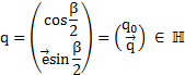
Where

 and
and  are known as the vector and scalar partis of
the quaternion recpectively. In attitude control aplications, the unit
quaternion represents the rotation from an inertial coordinate system
are known as the vector and scalar partis of
the quaternion recpectively. In attitude control aplications, the unit
quaternion represents the rotation from an inertial coordinate system  located at some point in the space (for
instance, the earth NED frame), to the body coordinate system
located at some point in the space (for
instance, the earth NED frame), to the body coordinate system  located on the center of mass of a rigid body.
If  is a vector
expressed in
is a vector
expressed in  , then its coordinates in
  are
expressed by:
are
expressed by:

Where  and
and  are the quaternions associated to vectors
  and respectively.
  denotes the quaternion multiplication and
  is the conjugate quaternion multiplication of q, defined as:

The rotation matrix C(q) corresponding to the attitude quaternion q, is computed as:

Where  is the identity matrix and
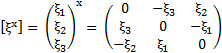
  is a skew symmetric tensor associated with the axis vector
  :
:
Thus, the coordinate of vector expressed in
the B frame is given by:

The quaternion attitude error used to
quantify the mismatch between two attitudes  and
and  is computed by:

3. Problem Statement
In the case of the attitude estimation, one seeks to estimate the attitude and accelerations of a rigid body. From now on it is assumed that the system is equipped with a tri axis accelerometer, three magnetometer and three rate gyros mounted orthogonally.
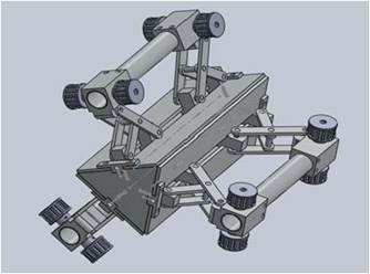
In this section we describe the body's kinematic of the model. In the present work, our typical capture configuration relies primarily on on the Robot of figure 1 equipped with twelve 1 inch diameter wheels driven by 3 DC gear head motors. The mechanical model is based on single pinion architecture suitable for light vehicles. The combination of this information jointly to knowledge a priori of the robot makes possible to obtain information on the mobile robots respect to the base.
The controller was able to set the power level to each motor independently, but there was no feedback loop based on tachometers, or current sensing. In order to estimate the attitude robot position with respect to an inertial frame, a module containing three rate gyros, three accelerometer and three magnetometer assembled in tri axis, are positioned near the centre of robot. Thus, the attitude for the articulation is estimated. The combination of this information jointly to knowledge a priori of the dynamic of the movement of the robot makes possible to obtain information of the attitude of the robot respect to the base.
The equation describing the relation between the quaternion and the body's kinematic is given in introducing the angular variation
 From this, it follows.
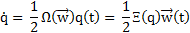
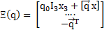
Where  y
y  are defined as:

The quaternion must be:

In the other hand, the matrix
has the relation:


Generally  , for any
  .
.

That is denoted like the orientation matrix 3-D of dimension 3x3.
3. 1. Modeling sensors
1) Rate
Gyros: The angular velocity  is measured by the rate gyros, which are supposed
to be orthogonally mounted. The output signal of a rate gyro is influenced by
various factors, such as bias drift and noise. Since an integration step is
required in order to obtain the current attitude quaternion (9), even the
smallest variation of the rate gyro measurement will produce a wrong estimation
of the attitude. The bias is denoted by
is measured by the rate gyros, which are supposed
to be orthogonally mounted. The output signal of a rate gyro is influenced by
various factors, such as bias drift and noise. Since an integration step is
required in order to obtain the current attitude quaternion (9), even the
smallest variation of the rate gyro measurement will produce a wrong estimation
of the attitude. The bias is denoted by  , belonging to space
  . The rate gyro measurements are modeled
by [7]:
. The rate gyro measurements are modeled
by [7]:


Where  and are
  supposed by Gaussian
white noises and
supposed by Gaussian
white noises and  is a diagonal matrix of time constants. In this case, the constant
  which has been set to 100 s.
The bias vector
which has been set to 100 s.
The bias vector  will
be estimated online, using the observer presented in the following section.
will
be estimated online, using the observer presented in the following section.
2) Accelerometers: Since the 3-axis accelerometer is fixed to the body, the measurements are expressed in the body frame B. Thus, the accelerometer output can be written as:

where  and
and  are the gravity vector and the
inertial accelerations of the body respectively. Both are expressed in frame N.
g = 9:81 m/sec2 denotes the gravitational constant and
are the gravity vector and the
inertial accelerations of the body respectively. Both are expressed in frame N.
g = 9:81 m/sec2 denotes the gravitational constant and  is the vector of noises that are supposed to be white Gaussian.
3)
Magnetometers: The magnetic field vector  is expressed in the N frame it is supposed to be
  . Since the
measurements take place in the body frame B, they are given by:
. Since the
measurements take place in the body frame B, they are given by:

Where  denotes the perturbing magnetic field. This perturbation vector is supposed to be modeled by Gaussian white noises.
4. Attitude's Estimation and Prediction
The attitude estimator uses quaternion representation. Two approaches are jointly used, namely a estimation with a constraint least-square minimization technique and a prediction of the estate at the instant k. The prediction is performed in order to produce a pseudo-estimate of the accelerations and the attitude quaternion. This prediction is driven by a estate which is obtained from the quaternion propagated through the kinematic equation and the one obtained via the constraint minimization problem.
Actually, this latter problem is divided in three steps. First, the body accelerations are estimated from the previously computed quaternion. Then, the influence of the body accelerations is predicted from the accelerometer measurements. Using these updated accelerometer measurements together with the magnetometer measurements, a pseudo-measure estate is estimated via an optimization technique. In this way, the quaternion that is obtained by the estimation with a constraint least-square is insensitive to the body accelerations. Thus, no assumptions of the weakness (or not) of the accelerations are done, and no switching procedure from one model to another one is necessary. Therefore, the main advantage of the approach presented in this paper compared to others approaches, is that the estimated attitude remains valid even in the presence of high accelerations over long time periods.
In this paper a critter
that takes in account the evolution of the attitude state via determination of  in the function
  is proposed. The minimum error is chosen, but
it takes in account the prediction of the state
is proposed. The minimum error is chosen, but
it takes in account the prediction of the state  and the
coefficients of weight for the state
and the
coefficients of weight for the state  and the
measures estimated (MesEstimated = MS) at the instant k.
and the
measures estimated (MesEstimated = MS) at the instant k.

with 
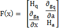
The process of Estimation and Prediction needs the determination of his gradient; this one is obtained by equation 19

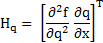
Similarly, is the obtention for the gradient of the state for the case of acceleration.
Finally, the total Gradient is obtained by the fusion between the calcule show for the quaternion case a the gradient omitted for the acceleration case.
Fort he prediction's process of , several technique have been validated, for purpose of simplicity, the prediction via
spline is chosen. Cubic spline is a spline constructed of piecewise third-order
polynomials wich pass through a set of n control points.
Suppose we are n+1 data points  such that.
 Then the coefficients of the vector exists cubic
polynomials with coefficients
Then the coefficients of the vector exists cubic
polynomials with coefficients 
 such that the following hold.
1) 
2) 
3) 
4) 
5) 
So we see that the cubic spline not only
interpolates the data but matches the first and second derivatives at
the knots. Notice, from the above definition, one is free to specify constrains
on the endpoints. The end point constrain  is chose.
The
estimation of the torque is part of another work that is in process and only we
present his basic model. Since the driver torque is not measured in line, we
introduce an estimator for  , Essentially, the estimated value of the driver
torque is
, Essentially, the estimated value of the driver
torque is

Where  is the torque in the steering column part and
  is the assist motor torque. In order that
  can be physically realizable (numerator degree
of the transfer function is always less or equal than denominator degree), it
is necessary to introduce a correction transfer function
can be physically realizable (numerator degree
of the transfer function is always less or equal than denominator degree), it
is necessary to introduce a correction transfer function  to maintain the properness. With this correction, the inverse transfer function becomes

5. Results
5. 1. Simulation Results
In this section, some simulation results are presented in order to show the performance of the proposed control laws. A rigid body with low moment of inertia is taken as the experimental system. In fact, the low moment of inertia makes the system vulnerable to high angular accelerations which proves the importance to apply the control.
The proposed technique
is compared to the existing methods (namely, the Multiplicative Extended Kalman
Filter (MEKF) and the Additive Kalman Filter (AEKF)). Initial conditions are
set to extreme error values in order to assess the effectiveness of attitude
estimation. These results are depicted in figure 2. The proposed method
performances are similar to those of the Extended Kalman Filter (Multiplicative
and Additive). However, for extreme errors the convergence rate for our
estimation-prediction is higher. For the movements, the acceleration is  (not weak case) and
the quaternion is arbitrary with q0 far from the initial conditions.
(not weak case) and
the quaternion is arbitrary with q0 far from the initial conditions.
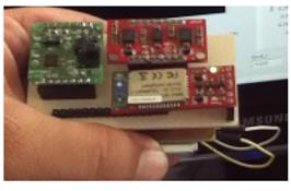
5. 2. Experimental results
The estimation methodology proposed in this work is implemented and evaluated in real time, in order to assess its effectiveness. For this purpose an embedded system was designed, and developed ( Figure 3). Special attention was paid to the low power consumption requirements and weight, leading to the selection of the Digital Signal Controller dsPIC which was used with a clock speed of 4MHz. It contains extensive Digital Signal Processor (DSP) functionality with high performance 16 bit microcontroller (MCU) architecture but without floating point unit.
The sensor suite is based on a sensor board equipped with a tri-axis accelerometer (ADXL135), a dual axis gyro (LPR530AL) and single axis gyro (LY 530ALH) and a tri-axis magnetometer (Micromag3). All sensors outputs are analog except the Micromag 3 which is digital and uses the Serial Peripheral Interface (SPI) bus system as underlying physical communication layer. The total system supply voltage is 3.3 V. The dimension and weight are 60x40x15mm and 60g, respectively. For purpose of validation A Commercial AHRS [9] is used to acquire the data instead of the MEMS sensors presented in section (III-A )(Robot showed in virtual reality figure 1).
(1) The AHRS (sensor module) was placed to a well known orientation q0 = [1 0 0 0]T (the AHRS is still in the horizontal and it is headed toward the magnetic north) which correspond to shoulder angular position:

(2) The AHRS is still at q0 for 10 s;
(3) The AHRS is placed at its initial angular position such that the final and initial orientations are identical;
(4) For the entire
simulation time span, the signal  is added to accelerometers channels (That is done
in order to show the ability of the proposed approach to estimate the
acceleration and in the same way to depict the insensibility to non-weak
acceleration).
is added to accelerometers channels (That is done
in order to show the ability of the proposed approach to estimate the
acceleration and in the same way to depict the insensibility to non-weak
acceleration).
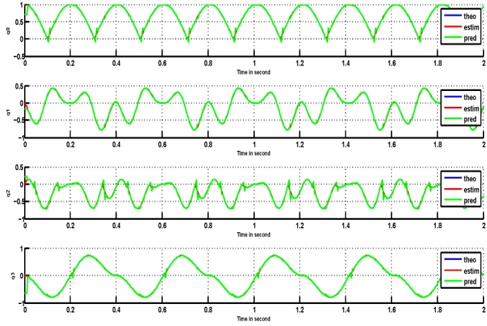
In Fig. 4, the estimated quaternion  and the measured quaternion are depicted. As expected, the attitude estimate reaches the true
attitude (which in this case it is well known and represented by: q0 = [1 0 0
0]T ) in suitable time for practical implementation. It can be noticed that
despite the noise, drift bias and non-weak acceleration introduced, the
evolution of the quaternion estimated reaches the values of the initial
attitude q0 = qf = [1 0 0 0]T.
and the measured quaternion are depicted. As expected, the attitude estimate reaches the true
attitude (which in this case it is well known and represented by: q0 = [1 0 0
0]T ) in suitable time for practical implementation. It can be noticed that
despite the noise, drift bias and non-weak acceleration introduced, the
evolution of the quaternion estimated reaches the values of the initial
attitude q0 = qf = [1 0 0 0]T.
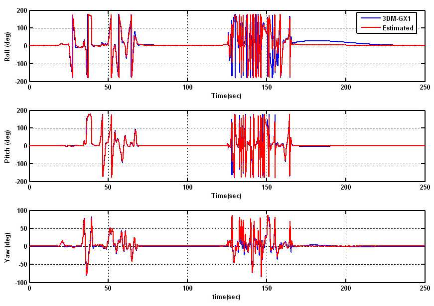
This AHRS also provides the Euler angles. The methodology of estimation and prediction are implemented in real-time using the LabView environment. Remember that the attitude estimate is computed using a unit quaternion formulation. For comparison purpose, the estimate quaternion is converted into Euler angles.
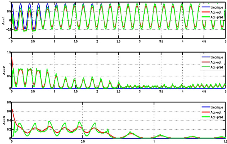
(b)
Figure 2. Simulation Study.
a) Estimationand Prediction of the Acceleration ( ,
, )
)
b) Estimation and Prediction of the Quaternion ( ,
, )
)
As can be shown, after large angular velocity change over a long period, the AHRS has a low convergence rate (approx.1 min) compared to the one achieved with our proposed methodology. On the other hand, this system doesn't provide the acceleration of the body so for validation we have done slowly movement and abrupt movement to appreciate the effect of the acceleration in our method. In figure 4 the global convergence of the estimation techniques is proved.
6. Conclusions
This paper presented a new strategy for attitude estimation of possibly non-symmetric rigid bodies. Two globally methods of calculation of the body's attitude are proposed, namely one methodology based in fusion data information provided by a tri-axis accelerometer, three magnetometer and three rate gyros mounted orthogonally jointly with prediction of the movement via cubic splines are studied and simulated. In order to achieve sub-degree accuracies in pitch and roll for ultra-short baseline attitude systems it is necessary to utilize a known bias algorithm. This necessitates the development of multiple antenna common oscillator GPS receivers, in this paper a bias algorithm is presented using low cost MEMs sensors, the results are very encouraging.
Furthermore, the attitude estimation is independents of the body's inertia. The numerical simulations have showed the effectiveness of the proposed methodologies and their robustness with respect to sensors noise and far initial points.
Moreover, the simplicity of the methodology makes it suitable for embedded implementation. This control estimation will be tested in real time application, choosing as application a mobile robots and the estimation of the signal in embedded technologies.
7. Acknowledgments
The authors would like to thank to the Instituto Politécnico Nacional (I.P.N.) - S.E.P.I. E.S.I.M.E. U.A and the S.I.P. for the projects 20150607, 20151980 and 20150901,CONACyT and the B.U.A.P. - F.C.E.
References
[1] Choo k., Fleet D. J., "People tracking using hybrid monte carlo filtering" Eighth International Conference on Computer Vision (ICCV'01) vol. 2, pp. 321, 2013.View Article
[2] Choukroun, D., "Novel methods for attitude determination using vector observations" Tesis de doctorado, Israel Institute of Technology, Haifa, Israel, 2003.View Article
[3] J.F Guerrero Castellanos, S. Lesecq, N. Marchand, J. Delamare, "A low-cost air data attitude heading reference system for the tourism airplane applications" IEEE - SENSORS, 2005.View Article
[4] J.W. Mills, "Lukasiewicz insect: The role of continuous-valued logic in a mobile robot's sensors, control, and locomotion" Proceedings of the International Symposium on Multiple-Valued Logic, Sacramento, CA, USA, pp. 258-263, 1993.View Article
[5] Lefferts, E.J., F.L. Markley y M.D. Shuster, "Kalman filtering for spacecraft attitude estimation" Journal of Guidance, Control, and Dynamics, vol. 5, no. 5, 417-429, 1982.View Article
[6] M., Gavrila BD., "The visual analysis of human movement: a survey" Computer Vision and Image Understanding, vol. 73, no. 1, pp. 88-98, 1999.View Article
[7] S. Ahrens, D. Levine, G. Andrews, and J.P. How., "Vision-based guidance and control of a hovering vehicle in unknown, gps-denied environments" Robotics and Automation, ICRA'09. IEEE International Conference, pp. 2643-2648, 2009.View Article
[8] Salcudean, S., "A globally convergent velocity obsever for rigid body motion" Automatic Control, IEEE Transactions, vol. 36, no. 12, pp. 1493-1497, 1991.View Article
[9] Sensors, MicroStrain Microminuature, 2013. View Article
[10] Shuster, M.D., "A survey of attitude representations" Journal of the Astronautical Sciences, vol. 41, no. 4, pp. 439-517, 1993.View Article
[11] Surya, P.N. Singh y J.Waldron Kenneth, "Attitude estimation for dynamic legged locomotion using range and inertial sensors" Robotics and Automation, ICRA'05, 2005.View Article
[12] Thienel, J. y R.M. Sanner, "A coupled nonlinear spacecraft attitude controller and observer with an unknown constant gyro bias and gyro noise" Automatic Control, IEEE Transactions, vol. 48, no. 11, pp. 2011-2014, 2003.View Article