International Journal of Mechanical Engineering and Mechatronics (IJMEM)
ISSN: 1929-2724

Volume 4 - Year 2017 - Pages 11 - 17
DOI: 10.11159/ijtan.2017.002
Nonlinear Analysis of Pull-In Voltage of Twin Micro-Cantilever Beams
M. Amin Changizi1, Ion Stiharu2
1 Knowledge Engineering, Intelliquip Co.
3 W Broad St, Bethlehem, PA 18018, USA
Achangizi@intelliquip.com
2 Department of Mechanical and Industrial Engineering, Concordia University
1455 De Maisonneuve Blvd. W., Montreal, Quebec, Canada, H3G 1M8
Istih@alcor.concordia.ca
Abstract - Micro-cantilever beams represent good
candidates for sensing applications due to their simple structure, predictable
response and ease to manufacture. The range of their applications covers
bio-engineering, telecommunications and automotive.
Both static and dynamic responses of micro-cantilever beams under various types of
loading were extensively studied during last several decades. The objective of
this work is to find a suitable model for the dynamic deflection of single and
double micro-cantilever beams while subjected to an electrostatic field and
evaluate the pull-in voltage. The model for this phenomenon is described by a
nonlinear differential equation (NDE). One of the further specific objectives
of this investigation is to study the critical pull-in voltage, i.e. the
voltage that is close to the values that set the micro-beam to an irreversible
instability status. This situation ends up with the failure of the beam when it
will touch the substrate. The pull-in voltage represents a major concern in
MEMS capacitive measurement based applications and it has been widely studied
in literature. Theoretical studies on large deflection of micro-cantilever
beams under the influence of an electric field were carried out. The
differential equation that models the dynamic behaviour of the micro-cantilever
beam under electrostatic loading is nonlinear and stiff. A simplified model for
a micro-cantilever beam could be represented as a single degree of freedom
(SDOF) mass-damper-spring. Maple® software includes an algorithm which is
called ISODE that can satisfactory solve numerically this stiff NDE. This
algorithm uses adaptive time-step that enables a feasible solution. Further,
the stiffness model base on the dynamic behaviour of twin micro-cantilever
beams was derived. The effect of application of the pull-in voltage is
numerically investigated. A close-form time response to step-voltage solution
is derived by Lie symmetry groups and the pull-in voltage calculated for an
undamped system. The solution is compared to the results numerically determined
by solving the ODE of the reduced form of the non-linear model.
Keywords: Pull-in Voltage, Twin Micro-Cantilever, Lie Symmetries.
© Copyright 2017 Authors - This is an Open Access article published under the Creative Commons Attribution License terms. Unrestricted use, distribution, and reproduction in any medium are permitted, provided the original work is properly cited.
Date Received: 2016-11-22
Date Accepted: 2017-03-02
Date Published: 2017-09-07
Nomenclature
- y(t) deflection
- t time
- ξ damping factor
 natural frequency of beam
- f(t) external force on beam
- m mass of beam
 absolute permittivity
- A area of the beam
- V applied voltage
- g original gap
 initial velocity of beam
 diffeomorphism functions
 - α parameter of the group
- U transformation operator
 infinitesimal transformation
 Constant numbers
 canonical coordinates
1. Introduction
Pull-in voltage represents an important parameter for micro-cantilever beams when subjected to local electric fields. The pull-in voltage dictates the limited performance of the investigated device that is the voltage at which the system becomes irreversible unstable. Following the equilibrium of forces of a lump mass model it has been found that [1] the micro-cantilever beam subjected to the pull-in voltage will be attracted by the substrate and will reach a distance the corresponds to 2/3 of the initial gap, moment at which the structure will become irreversible unstable. The open literature includes many contributions that report the results of the theoretical and experimental findings in conjunction with the operation of micro-fabricated cantilever structures interacting with different types of electric fields.
The pull-in voltage can be also calculated from the differential equation that describes the model of the dynamic behaviour of the micro-cantilever beam subjected to an electrostatic field.
There are several methods to obtain the governing differential equation. The common methods are using either Hamiltonian [2] or energy [3] methods. Many researchers used several different approaches to linearize and simplify the governing equations given their high non-linearity. The Finite Element Method (FEM) was extensively used to numerically find the pull-in voltage [4]. Taylor series are used to linearize the governing differential equation in [5]. Perturbation method [6] and Runge-Kutta algorithms represent other approaches of solving the derived Duffing equations that are used to model the dynamic behaviour of the micro-cantilever beam subjected to both electric field and harmonic excitations. These methods are applicable to a Duffing equation as it is not a stiff equation. Another approach assumes small deflections of the structures involved and the results are compared with the experimental data [1]. This method is not very suitable due to the nature of the large deflection of micro-cantilever beams in electric field [7]. Continuum theory while using dimensionless parameters and orthogonal functions type Taylor series [8] were employed in the derivation of the governing equations of the dynamic behaviour of the micro-cantilever beam. In the small deflection approach, the error is found to be directly proportional with the length of the beam and decreases when the structure is excited at a difference of potential significantly below the pull-in voltage value [9]. The effects of variation of the width and thickness of the micro-cantilever beam on the resonant frequency were the subject of several theoretical and experimental studies [10].
It is to be mentioned here that the pull-in between two flexible surfaces was not reported as studied so far in the open literature.
2. Driving Governing Equations
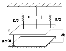
The dynamic behaviour of micro-cantilever-type actuators under electrostatic filed by assuming that continues media is a simplified system the lump mass. We also assume that the twin micro-beams are identical and they would perform dynamically same. These hypothesis can be described like in equation (1). This assumption simplifies the analysis by losing some accuracy. Figure 1 illustrates the considered simplified model by using a mass-spring-damper system:
f(t) in the equation (1) represents
the electrostatic force, m is the mass of the beam, y(t) shows the deflection
of micro-cantilever beam and ξ is the damping factor ![]() .
.
The value of the force exerted due to the electrostatic effect between the two parallel surfaces is significant in micro-structures. Its expression can be obtained from the energy balance and is given by:
![]() is absolute permittivity of the medium between the surfaces, g is initial distance between beam and substrate, A is area of the beam and V is the applied voltage.
is absolute permittivity of the medium between the surfaces, g is initial distance between beam and substrate, A is area of the beam and V is the applied voltage.
The equation (1) can be rewritten as:
where the initial conditions (initial speed at reference position and time) for this ODE are assumed to be the following:
 and
and 
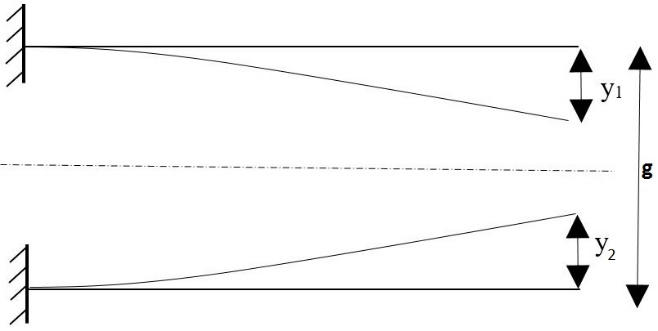
If the substrate is an identical micro-cantilever beam like the one above it, the system will be constituted of two beams symmetrically positioned and parallel. Fig. 2.
If one assumes that deflection of top beam is y1 and deflection of lower beam is y2 the differential equations of micro-cantilever beams can be written as following:

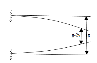
By assuming that
two beams are identical, one can assume that all parameters of the two beams
are same (![]() =
= ![]()
![]() ,
, ![]() ,
, ![]() and
and ![]() . The system of ODEs can thus be reduced to one
ODE as following:
. The system of ODEs can thus be reduced to one
ODE as following:
The micro-cantilever beams are shown in Fig.3.
Initial conditions of beams are same as in (4).
3. Theory
There is no close form analytical formulation in the best of our knowledge to express the solution of the non-linear equation (6) [11]. The micro dimensions of the involved structures contribute to the stiffness of the ODE. The current approach used to solve the equation (6) is the numerical one. The present study proposes a method of reduction of the order of the governing equation using Lie symmetry method, transforming the second order ODE into a first order ODE that can subsequently be solved in an easier manner. In the subsequent paragraphs, the terminology involved by the use of Lie symmetry method requires is presented.
The point transformation maps a point (x, y) on a specific curve into a point (x1, y1) as below:

where ϕ, ψ are
diffeomorphism functions ![]() .
A symmetry transformation preserves the shape of a given curve and maps this
curve on itself. A transformation like (7) which satisfies the group properties
is called a one-parameter group while α is called the parameter of the
group.
.
A symmetry transformation preserves the shape of a given curve and maps this
curve on itself. A transformation like (7) which satisfies the group properties
is called a one-parameter group while α is called the parameter of the
group.
An infinitesimal transformation for a one-parameter group is defined as:
Where:

U is the transformation operator on the function f. The necessary and sufficient condition for a group to be a symmetry transformation for a function f=f(x,y) is that:

The condition (10) will be used to calculate the infinitesimal transformations of the ODE (6). The prolonged vector method [12] is common way to calculating the Lie symmetry of a group.
For a second-order ODE like below:
An infinitesimal transformation is applied as an operator on itself and, both functions ξ and η defined in (9), must satisfy the following equality [11]:


Subsequently, ξ and η can be calculated by decomposed [3-6] into a system of partial differential equations. The following Lie symmetries which including rotation, translation and scaling was considered to calculate ξ and η.


By substituting the equations (13) in (12):


Where ![]()
The coefficients of ![]() in left hand and right-hand terms must be equal:
in left hand and right-hand terms must be equal:

Therefore:

Following the same procedure, the coefficients of in left hand and right hand terms are equated:

By simplification:

The coefficients of x in left hand and right hand terms must also be equal, then:

Considering the expressions (16), (17) and (20), the equation (14) becomes:

With these considerations:

From the above calculations, it can be concluded that the equation (9) has the following infinitesimal form:

Any pair of functions r(x,y), s(x,y) satisfying the following conditions forms canonical coordinates:


The equation (23) satisfies the conditions (24) and therefore, ξ(x,y)=1,η(x,y)=0.
The canonical coordinates for a function f(x,y) can be found from the characteristic equation [11]:
The solution of the above ODE is r(x,y):

and s(x,y) will be:
Through adequate selection of variables, the order of the ODE can be reduced. From (25), (26) and (27) the canonical coordinates can be calculated as:

Considering:

The function ![]() is defined as:
is defined as:

The equation can be expressed by contact form [11] as:

or:

The canonical coordinates and ![]() can be calculated by using the
relations (25), (26) and (27). By considering v as a new variable and
substituting in the ODE (6), the new generated ODE will have one order less
than the original one.
can be calculated by using the
relations (25), (26) and (27). By considering v as a new variable and
substituting in the ODE (6), the new generated ODE will have one order less
than the original one.
Substituting (30), (31) and (32) in (6) yields:
The equation (33) is a first order ODE and ![]() it is the initial condition.
it is the initial condition.
According the recent investigations
there is no one-parameter group that satisfies the symmetric condition (33).
For this reason, no analytical solution for this ODE can be formulated. One can
show that there is no transformation of scaling or rotation symmetry for (6)
[11]. This equation has a singularity (where ![]() ) and the integration in close
form is therefore impossible. Hence, the numerical method approach is used in
solving the first order differential equation.
) and the integration in close
form is therefore impossible. Hence, the numerical method approach is used in
solving the first order differential equation.
4. Results
For both scenarios (one beam and two-beam setups) a numerical analysis is performed. The constructive parameters for the polysilicon beams are 200μm length, 20μm with and 2μm thickness with a Young modulus of 169 MPa and gap distance is 10μm. For a more detailed insight in the method of analysis one can refer to [11].
The value of pull-in voltage is calculated by assuming that nonlinear part of the equation (33) to be zero, as follows:
Pulling voltage numerically determined from the bellow graphs is 129.055 V for a two-beam setup and 182.511 V for one beam [11]. The pull-in value calculated from (34) shows that, for the two-beam setup, the error of the exact solution with respect to the numerical solution is 0.104%. For the single beam, using almost similar equation the calculated error increases slightly to 0.449%. The value of the deflection, y, used in the equation (34) for two parallel beams was considered half of through deflection in the case of one beam.
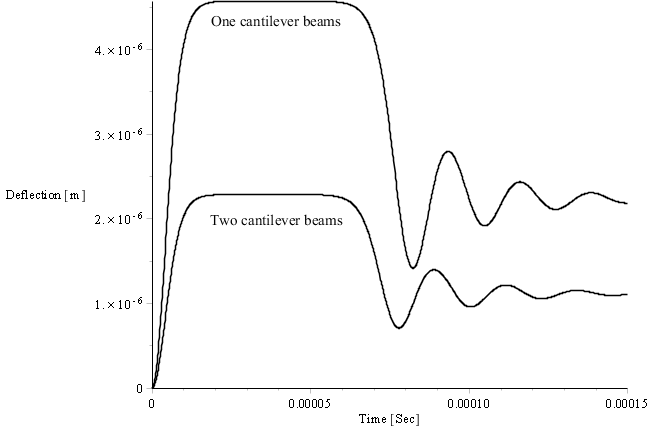
The one beam configuration as the two beam configuration exhibit same behaviour as illustrated in Fig. 4. When excited with a voltage close to the pull-in voltage, the beams will deflect to a maximum deflection representing 0.45 of the original gap for one beam and 0.225 of the original gap for two beams configuration. After a period of stall, the beams will settle with oscillations versus a position that corresponds to 0.225 of the original gap for one beam configuration and 0.1175 for two beam configuration.
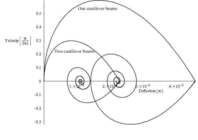
The stall is seen as well in the phase diagram for one and two beam configurations beams.
5. Conclusions
The dynamic behaviour of a micro-cantilever beam under the influence of an electric field and excited by an electric potential close to the pull-in voltage was investigated analytically and the results validated experimentally with data from the literature. A particular exact solution of the governing equation was found using the Lie symmetry method, by reducing the order of the initial ODE.
The pull-in voltage of one and two-beam setups was determined both analytically and numerically and the error between the two methods calculated. An experimental validation of one beam pull-in to a rigid substrate was carried out in the laboratory and the result show that the model is accurate within 96% [13]. It is expected that the two beam model that used same constitutive formulation would yield similar accuracy range as same assumptions were made in the modeling. The findings can be used to model and design micro-flow sensors, wind sensors or other physical quantities which are encountered in gas flow.
References
[1] I. Schiele, J. Huber, B. Hillerich, and F. Kozlowski, "Surface-micromachined electrostatic micro-relay," Sensors & Actuators: A. Physical, vol. 66, pp. 345-354, 1998. View Article
[2] Y. C. Hu, C. M. Chang, and S. C. Huang, "Some design considerations on the electrostatically actuated microstructures," Sensors & Actuators: A. Physical, vol. 112, pp. 155-161, 2004. View Article
[3] C.-K. Chen, H. Lai, and C.-C. Liu, "Application of hybrid differential transformation/finite difference method to nonlinear analysis of micro fixed-fixed beam," Microsystem Technologies, vol. 15, pp. 813-820, 2009.F View Article
[4] H. Busta, R. Amantea, D. Furst, J. M. Chen, M. Turowski, and C. Mueller, "A MEMS shield structure for controlling pull-in forces and obtaining increased pull-in voltages," Journal of Micromechanics and Microengineering, vol. 11, pp. 720-725, 2001. View Article
[5] M. I. Younis, E. M. Abdel-Rahman, and A. Nayfeh, "A reduced-order model for electrically actuated microbeam-based MEMS," Journal of Microelectromechanical Systems, vol. 12, pp. 672-680, 2003. View Article
[6] W. Zhang, R. Baskaran, and K. L. Turner, "Effect of cubic nonlinearity on auto-parametrically amplified resonant MEMS mass sensor," Sensors & Actuators: A. Physical, vol. 102, pp. 139-150, 2002. View Article
[7] M. Amin Changizi, "Geometry and Material Nonlinearity Effects on Static and Dynamics Performance of MEMS," Ph.D. Thesis, Concordia University, Montreal, Canada, 2011. View Article
[8] J. H. Kuang and C. J. Chen, "Dynamic characteristics of shaped micro-actuators solved using the differential quadrature method," Journal of Micromechanics and Microengineering, vol. 14, pp. 647-655, 2004. View Article
[9] E. S. Hung and S. D. Senturia, "Extending the travel range of analog-tuned electrostatic actuators," Journal of Microelectromechanical Systems, vol. 8, pp. 497-505, 1999. View Article
[10] S. Chowdhury, M. Ahmadi, W. C. Miller, "A closed-form model for the pull-in voltage of electrostatically actuated cantilever beams," Journal of Micromechanics and Microengineering, vol. 15, p. 756, 2005. View Article
[11] M. Amin Chanzgizi, I. Stiharu, “Lie group analysis of non-linear dynamic of micro structures under electrostatic field,” Journal of Computational Methods in Sciences and Engineering, vol. 15, no. 3, pp. 327-338, 2015. View Article
[12] P. J. Olver, S. Axler, F. W. Gehring, and K. A. Ribet, Applications of Lie groups to differential equations. Springer Verlag, 2000. View Book
[13] M. Amin Changizi, I. Stiharu, “Sensitivity Analysis of the Non-Linear Deflection of Non-Straight AFM Micro-Cantilever,” Journal of Advanced Microscopy Research, vol. 7, no. 1, pp. 51-63(13), 2012. View Article